Device with additional restoring force on the gas pedal based on the deviation of a vehicle parameter from the set value

a technology of vehicle parameter and gas pedal, which is applied in the direction of mechanical control devices, manual control with single controlling member, instruments, etc., can solve the problems of gas reduction, ineffective force exerted by the driver, and inability of the driver to increase the speed in excess,

Inactive Publication Date: 2010-08-10
CONTINENTAL TEVES AG & CO OHG
View PDF22 Cites 31 Cited by
  • Summary
  • Abstract
  • Description
  • Claims
  • Application Information

AI Technical Summary

Benefits of technology

[0010]An object of the invention is to describe improvements of the known constructions that allow reducing the manufacturing costs for the device, improving the reliability of the mode of operation of the device and additionally introducing favorable features that simplify handling the device in practical operations. Details relating to the problems of the prior art devices can be seen in FIGS. 8a and 8c in connection with the associated description.
[0046]It is also important for the invention that it is not limited to leading a driver to the appropriate or prescribed speed of a vehicle by warning the driver upon application of the accelerator pedal that the necessary speed is exceeded or imparting to the driver the impression that the accelerator pedal has already reached the position the driver desires. Rather, the object of the invention can be favorably implemented also in the actuation of other control elements of the vehicle such as the brake pedal. The additional force resetting the brake pedal cannot only depend on the appropriate actuation of the brake itself (e.g. when starting to drive). Rather, the additional resetting force at the brake pedal (or also at the accelerator pedal) can also be controlled by driving-dynamics parameters such as ESP, if a driver wishes to brake too vigorously or to ride too rapidly into a curve. The design of the devices of the invention becomes particularly simple when the braking operation or the change in speed is not introduced directly into the pedal, but when the pedal position is scanned by means of sensors, as is the case e.g. in an electromechanically or electrohydraulically operating brake system.

Problems solved by technology

When the actual speed deviates further from the nominal speed, a condition as shown in FIG. 3 is adapted, where the adjusting lever is returned counterclockwise by the control lever, with the result that the gas is reduced and the force exerted by the driver becomes ineffective.
It is not possible for the driver to increase the speed in excess of the adjusted speed value in case of need.
As a result, the counterforce rises in dependence on the difference between actual and nominal speeds, an abrupt increase of the restoring force is not intended.
This prior art device suffers from the following disadvantage: initially, the force of the spring counteracts the restoring force of the spring, then becomes zero, and subsequently acts in dependence on the difference of speeds rising in the direction of the restoring force.
It has shown that the prior art constructions are rather complicated and costly and do not satisfy a number of demands placed in practical operations (cf. e.g. the demanded course of curve in FIG. 8b).

Method used


Image

  • Device with additional restoring force on the gas pedal based on the deviation of a vehicle parameter from the set value
  • Device with additional restoring force on the gas pedal based on the deviation of a vehicle parameter from the set value
  • Device with additional restoring force on the gas pedal based on the deviation of a vehicle parameter from the set value

Examples


embodiment 1

According to FIG. 1

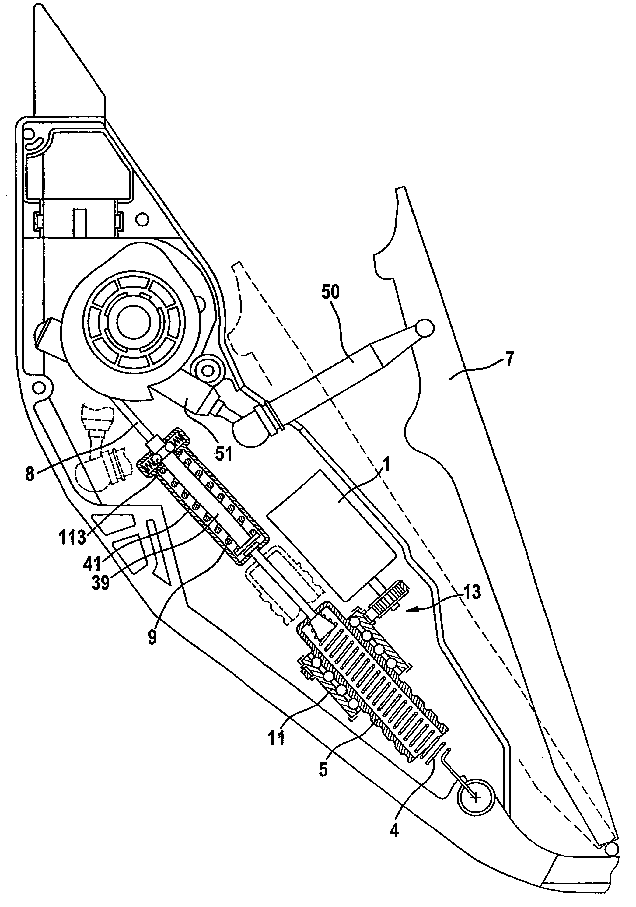
[0078]A fixed or a displaceable stop is used in some of the embodiments suggested herein below. Depending on the position of the stop, the engine torque acts in a defined pedal position in opposition to the pedal force or with respect to the stop. It is not only necessary to adapt the position of the stop to the desired driving speed but also to the driving situation. The stop is an adjustable rope slack in another solution. Different therefrom, the following function without a stop is proposed in the embodiment 1.

[0079]In FIG. 1 a pedal board 7 is articulated at a housing 23 of a pedal module. A cam plate 3 is rotatably arranged in housing 23. A coupling lever 50 cooperating with a turning lever 51 fixed to the cam plate makes catch at the pedal lever 7 configured as a board. It can be seen that the cam plate 3 is turned clockwise upon a counterclockwise rotation of the pedal lever 7. A restoring spring 4 which is referred to as return spring or retracting spring...

embodiment 2

According to FIG. 2a and FIG. 2b

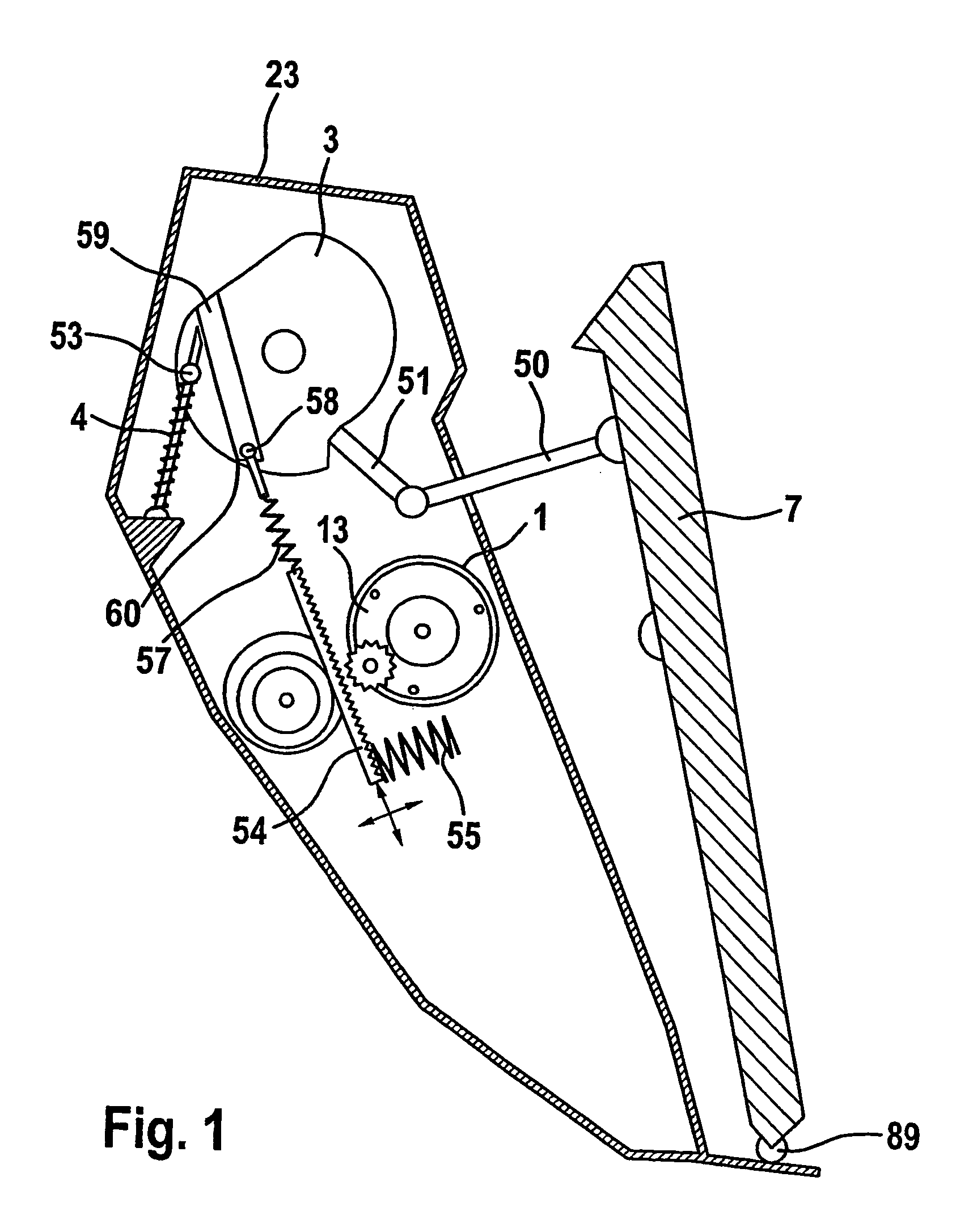
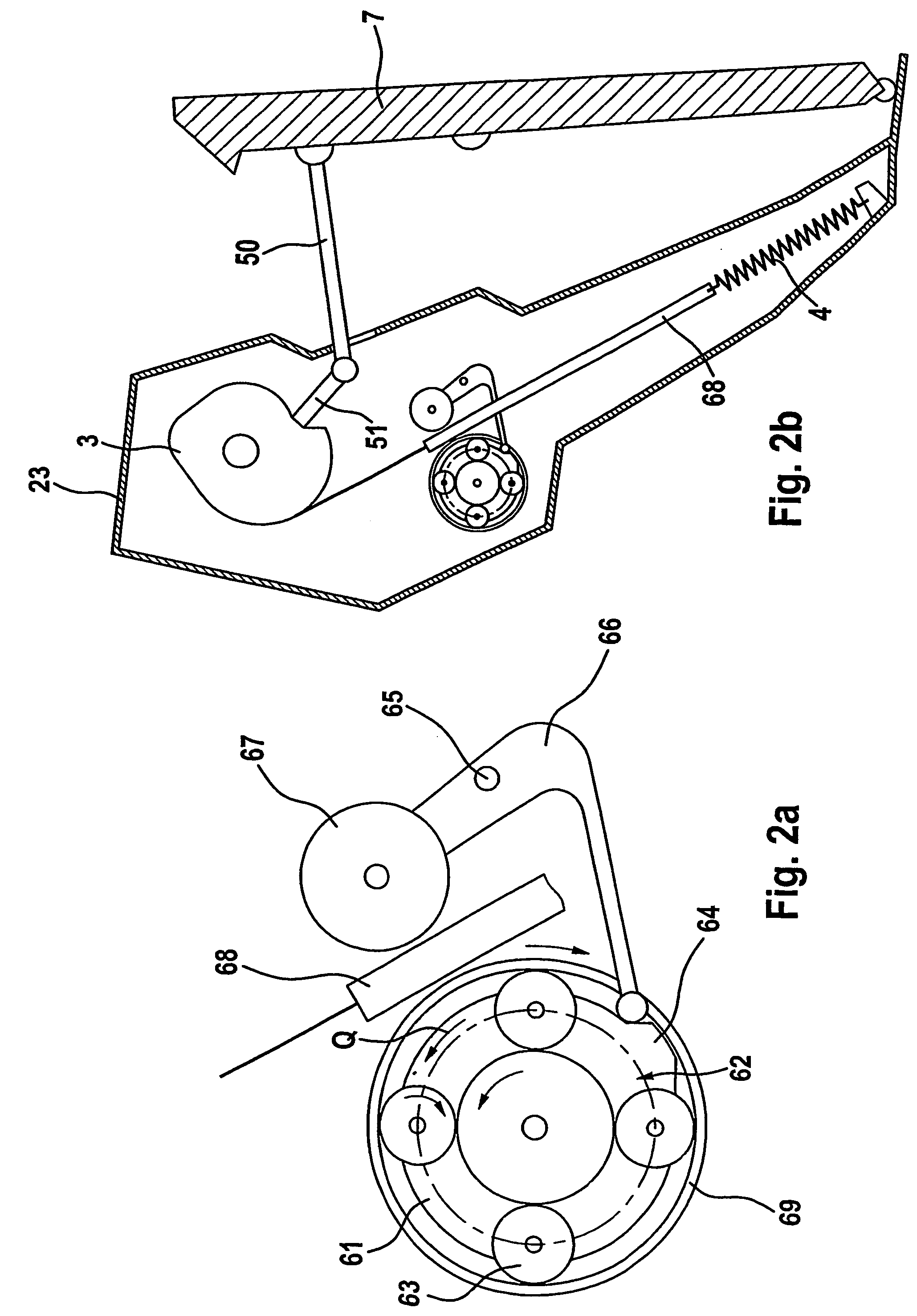
[0085]A fixed or a displaceable stop is used in some of the embodiments that will be suggested hereinbelow. Depending on the position of the stop, the motor torque acts in opposition to the pedal force or with respect to the stop in a defined pedal position. It is not only necessary to conform the position of the stop to the desired driving speed but also to the driving situation. In another solution, the stop is realized by an adjustable slack of rope. Different herefrom, the following function that does not provide for a stop is suggested in the embodiment 2.

[0086]The basic design of the embodiment shown in FIG. 2 again corresponds largely to the design according to FIG. 1 and shall not be explained more closely. When the motor (not shown in FIG. 2) is started in the embodiment of FIG. 2, a planet carrier 61 of the planetary gearing illustrated in FIG. 2a will turn in the plotted direction Q. The result is that the pressing roller 67 is urged again...

embodiment 3

According to FIG. 3a to FIG. 3c

[0100]The Force-Feedback unit (hereinbelow called FFE) shown in the drawings (see especially FIG. 3a) is connected to the accelerator pedal 7 at the point where the translation motion of the pedal or the pedal linkage (e.g. the coupling lever 50 in FIG. 2) is converted into a rotation. This point may e.g. be the axis of rotation of the pedal lever 7 or the axis of rotation of the cam plate 3 (cf. FIG. 1). Normally, it is the point where likewise the sensor for determining the angle of rotation is connected.

[0101]The sketches are only meant to illustrate the mode of operation, in all other respects the mechanics shown in FIGS. 3a to 3c is preferably integrated into the pedal module, and a housing 23 generally bounds the pedal module. The pedal module typically accommodates the restoring spring that resets the pedal 7 as a standard, a cam plate deviating the force of the restoring spring, and a coupling lever that transmits the force of the restoring sp...


PUM


Abstract

It is known in the art to apply a counterforce, which opposes the actuating force, onto an accelerator pedal of a vehicle in the event that the vehicle, with respect to a vehicle parameter, sufficiently deviates from the nominal value. The parameter can be the speed or the measured distance from vehicles driving ahead.The invention discloses a series of embodiments that satisfy especially easily and reliably the defined requirements for applying the counterforce to the pedal.

Description

TECHNICAL FIELD[0001]The present invention relates to a device for controlling a parameter of a motor vehicle (e.g. the speed of a vehicle), which includes a control element configured as a pedal. The fuel supply to the engine and, thus, the driving speed of the vehicle is controlled by way of the control element (e.g. the accelerator pedal or brake pedal) (or the speed is reduced by way of activation of the brake system). For safely and duly driving a vehicle, it is very important to stick to an appropriate and / or prescribed speed of a vehicle. To detect the instantaneous speed of a vehicle, the driver must read the speed from a speedometer in displays known in the art. While the driver is reading this measuring instrument and evaluates the result, it is possible for him / her only to certain limits to pay attention to the traffic.[0002]Hence, care must be taken in designing a display system for the driving speed of a vehicle, in particular, that the reading operation, on the one han...

Claims


Application Information

Patent Timeline
Patent Type & Authority Patents(United States)
IPC IPC(8): G05G1/30B60K26/02B60K31/04B60K31/18B60T7/04B60T7/06F02D11/10G05G5/03G05G7/04
CPCB60K26/021B60T7/04B60T7/042G05G1/30G05G5/03Y10T74/20888Y10T477/817F02D11/105
Inventor RITTER, WOLFGANGVON HAYN, HOLGERSCHONLAU, JURGENQUEISSER, TORSTENKLIMES, MILANRUFFER, MANFREDHAVERKAMP, MARTINGORLACH, JOHANNESKROLL, WOLFGANGSCHIEL, LOTHAR
Owner CONTINENTAL TEVES AG & CO OHG
Why Eureka
Try Eureka