Suspension strut for use with a compressible magnetorheological fluid

a magnetorheological fluid and suspension strut technology, applied in the direction of shock absorbers, magnetic bodies, transportation and packaging, etc., can solve the problems of reducing the life of the vehicle frame, affecting the cargo of passengers, and affecting the health of passengers,

Active Publication Date: 2010-08-10
HORSTMAN
View PDF5 Cites 93 Cited by
  • Summary
  • Abstract
  • Description
  • Claims
  • Application Information

AI Technical Summary

Benefits of technology

[0009]A strut for an active suspension system provides electronic control for both the force applied by the strut and the dampening characteristics of the strut. A compressible fluid is used within the strut, and preferably includes a compressible base fluid and electromagnetic field responsive particles which are suspended in the compressible base fluid. The electromagnetic field responsive particles are preferably closely matched in density and modulus of elasticity to that of the compressible base fluid to prevent sedimentation of the particles and to maintain the elasticity of the compressible fluid. The amount of compressible fluid within the strut is electronically controlled to determine the force applied by the strut, and a field strength applied to the compressible fluid in a fluid flow passage is electronically controlled to determine the dampening characteristics of the strut. The strut has an inner bore which defines a cylinder. A sleeve is disposed inside of the cylinder to define a primary fluid chamber, with an upper portion and a lower portion. A secondary fluid chamber is defined by the annular space between the exterior of the sleeve and the bore defining the cylinder. The compressible fluid is disposed within the primary and secondary chambers. Fluid displacement members are moveably extensible into each of the primary fluid chambers, and respective seals sealingly engage between heads of each of the cylinders and the fluid displacement members to retain the compressible fluid within the cylinders. The control valves are operated to apply fluid pressure from the accumulator to the cylinder chambers to determine the values for the spring rate coefficients and dampening coefficients of the struts. An electromagnetic field generator is preferably provided by an electric coil disposed exteriorly about the sleeve for providing an electromagnetic field in the secondary chamber to control the flow characteristics of the compressible fluid within the secondary chamber.
[0012]The struts for use in such a suspension system preferably have pistons mounted to respective fluid displacement members to divide the cylinder chambers into two opposed chambers. The dampening pistons are moveable with the fluid displacement members within the cylinder chambers. Flow paths are provided to opposite sides of the pistons so that fluid flow occurs between the two opposed pressure chambers of respective ones of the cylinder chambers. The fluid mass in the two opposed chambers can be changed using a control valve or with pulse width modulated charge and discharge valves. The compressibility of the fluid determines a spring rate coefficient, and the flow paths to opposite sides of the pistons determine dampening coefficients for the struts. Thus, the struts have respective spring rate coefficients and dampening coefficients and the capacity to vary the spring rate coefficient and the dampening coefficient all in a single unit. For high-frequency motion, the passive dampening features of the strut can be relied on, such that energy is not expended trying to generate all the strut forces by active means. Such struts offer direct replacement for traditional spring / shock absorber units as well as in-line MacPherson strut spring / shock configurations. Suspension systems using such struts can provide higher performance response speeds, greater dampening power, and adjustable spring and dampening rate coefficients to maintain effective usage of the full strut travel while accommodating variations in both empty and loaded vehicle weights, and for dynamic loads.

Problems solved by technology

Vehicle ride characteristics have complex dynamics characterized by nonlinearities, vehicle roll and pitch, vehicle flexibility effects, varying parameters, unknown friction, deadzones and high amplitude disturbances.
Excess vibration results in artificial vehicle speed limitations, reduced vehicle-frame life, biological effects on passengers and detrimental consequences to cargo.
Present automobile suspension systems traditionally use passive suspension systems which can only offer a compromise between the two conflicting criteria of comfort and performance by providing spring and dampening coefficients of fixed rates.
For example, sports cars usually have stiff, harsh, performance suspensions with poor ride quality, while luxury sedans typically have softer suspensions with poor road handling capabilities.
Due to the demands of increased fuel mileage and decreased emissions, passenger and commercial vehicles are becoming lighter, which results in the differences between laden and unladen weights of the vehicles becoming so broad that traditional suspension systems are unable to span the load range effectively, causing serious degradation in performance of the vehicle ride quality, load handling and control.
However, active systems typically require large power inputs to provide an actuator that is quick enough to compensate for impacts and vibrations which occur at desired traveling velocities over rough terrain.
The power requirements for such fully active suspension systems are generally prohibitive.
Although active control systems have been utilized to apply force to struts, that is, to add energy to the struts of suspension systems to prevent vehicle roll, they have not been combined with active dampening.
Prior art suspension systems which use ER and MR fluids have encountered several problems which have prevented their use in struts.
However, over relatively short periods of time, as compared to the typical service life of strut components for vehicle suspension systems, the ferrous particles have settled out of suspension in the base fluids rendering the respective electric field and magnetic field controlled valving schemes for determining the dampening characteristics of struts inoperable.
Ferrous particle sediments have also damaged strut seals where strut rods pass from within strut cylinders to exterior suspension components.

Method used


Image

  • Suspension strut for use with a compressible magnetorheological fluid
  • Suspension strut for use with a compressible magnetorheological fluid
  • Suspension strut for use with a compressible magnetorheological fluid

Examples


Embodiment Construction

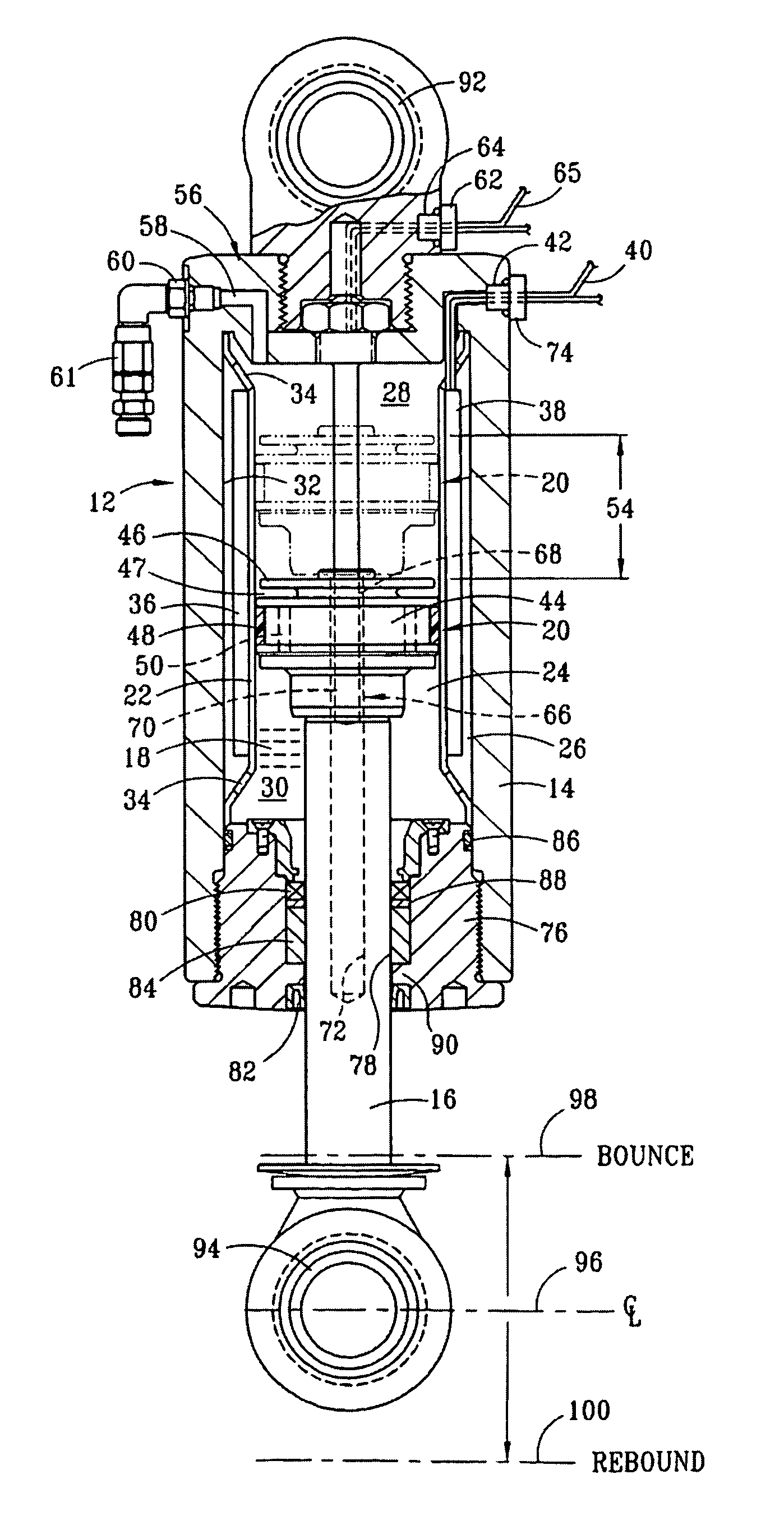
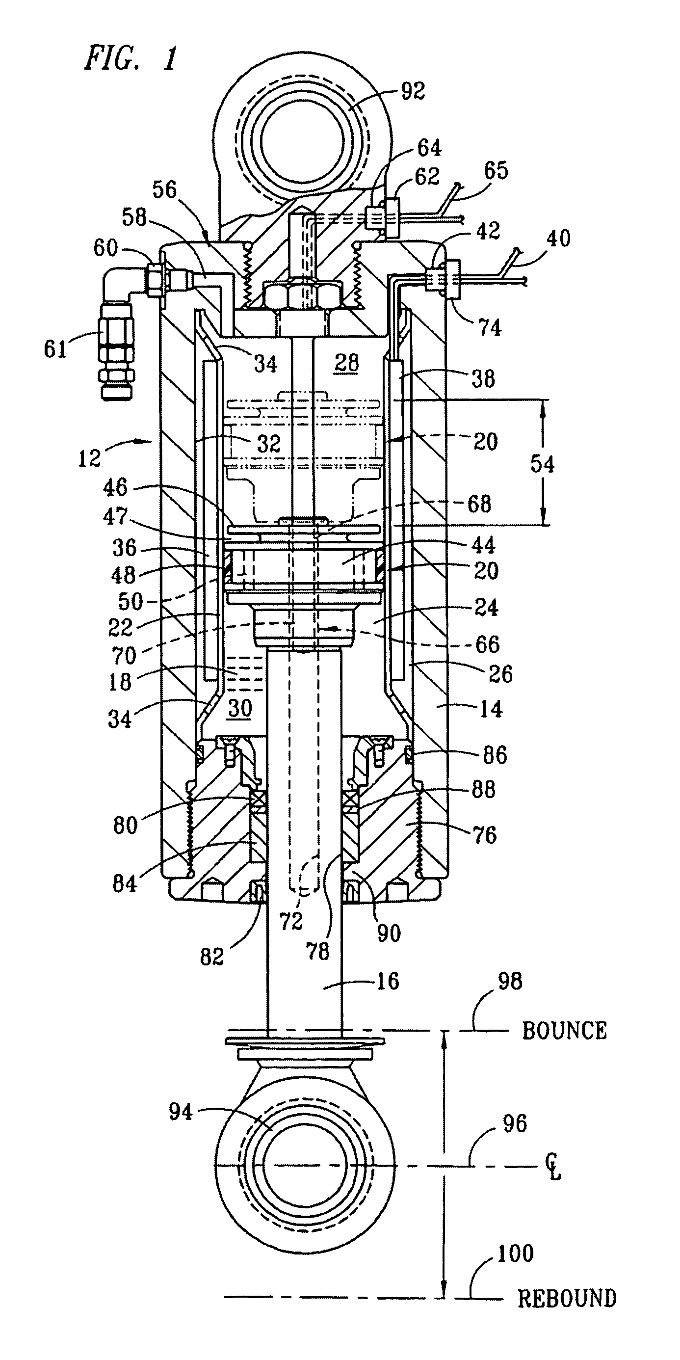
[0025]FIG. 1 is a partial longitudinal section view of a strut 12 having a cylinder 14 and piston 16. Preferably, the piston member 16 is provided by a cylindrically-shaped rod, which provides a displacement member for displacing fluid within the cylinder 14. A compressible fluid magnetorheological (“MR”) fluid 18 is disposed within the cylinder 14, and pressure of the compressible fluid 18 within the cylinder 14 applies force across a cross-sectional area of the piston 16. A damper element 20 is secured to an inward end of the piston 16. A sleeve 22 is rigidly mounted within the cylinder 14 to define a primary fluid chamber 24 and a secondary fluid chamber 26. The primary fluid chamber 24 is preferably disposed interiorly within the secondary fluid chamber 26. The primary fluid chamber 24 has a first region 28 and a second region 30 defined on opposite sides of the damper element 20, with the first region 28 preferably being inward of the second region 30, defined relation to an ou...


PUM


Abstract

A strut (12) is configured for an active suspension system (142) which provides electronic control for both the force applied by the strut (12) and the dampening characteristics of the strut (12). A compressible fluid (18) is used within the strut (12), and preferably includes a compressible base fluid and electromagnetic field responsive particles (132) which are suspended in the compressible base fluid. The electromagnetic field responsive particles (132) are preferably closely matched in density and modulas of elasticity to that of the compressible base fluid to prevent sedimentation of the particles (132) and to maintain the elasticity of the compressible fluid (18). The amount compressible fluid (18) within the strut (12) is electronically controlled to determine the force applied by the strut (12) and a field strength applied to the compressible fluid in a fluid flow passage is electronically controlled to determine the dampening characteristics of the strut (12).

Description

CROSS-REFERENCE TO RELATED APPLICATION[0001]The present application claims priority as a Continuation Application of U.S. application Ser. No. 10 / 786,817, filed Feb. 24, 2004, invented by Leo W. Davis, and entitled “Compressible Fluid Compressible Magnetorheological Suspension Strut,” and issued as U.S. Pat. No. 7,413,063 on Aug. 19, 2008, both of which claim priority as Continuation-in-Part Applications of U.S. Provisional Patent Appl. Ser. No. 60 / 449,761, filed Feb. 24, 2003, invented by Leo W. Davis, and entitled “Compressible Fluid Compressible Magnetorheological Suspension Strut.”TECHNICAL FIELD OF THE INVENTION[0002]The present invention relates in general to suspensions for vehicles, and in particular to suspension struts which are electronically controlled.BACKGROUND OF THE INVENTION[0003]Prior art suspension systems have been provided for motor vehicles to isolate the vehicle frame, or chassis, from impacts and vibrations resulting from vehicle wheels traversing uneven terr...

Claims


Application Information

Patent Timeline
Patent Type & Authority Patents(United States)
IPC IPC(8): F16F9/53
CPCB60G17/06B60G17/08C10M171/001F16F9/53H01F1/447B60G2400/64B60G2500/106C10N2230/60C10N2240/205C10N2030/60C10N2040/185
Inventor DAVIS, LEO W.
Owner HORSTMAN
Why Eureka
Try Eureka