
Electrical installation with a cooling element and method for operating said installation

a technology of cooling element and electric installation, which is applied in the field of electric installation to achieve the effects of high operational reliability, low cost and high current-carrying capacity

Active Publication Date: 2010-08-10
HITACHI ENERGY LTD
View PDF19 Cites 6 Cited by
  • Summary
  • Abstract
  • Description
  • Claims
  • Application Information

AI Technical Summary

Benefits of technology

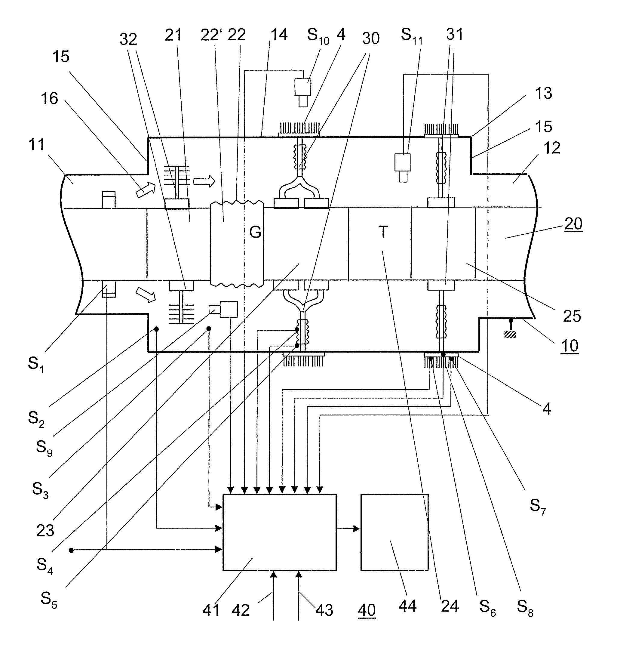
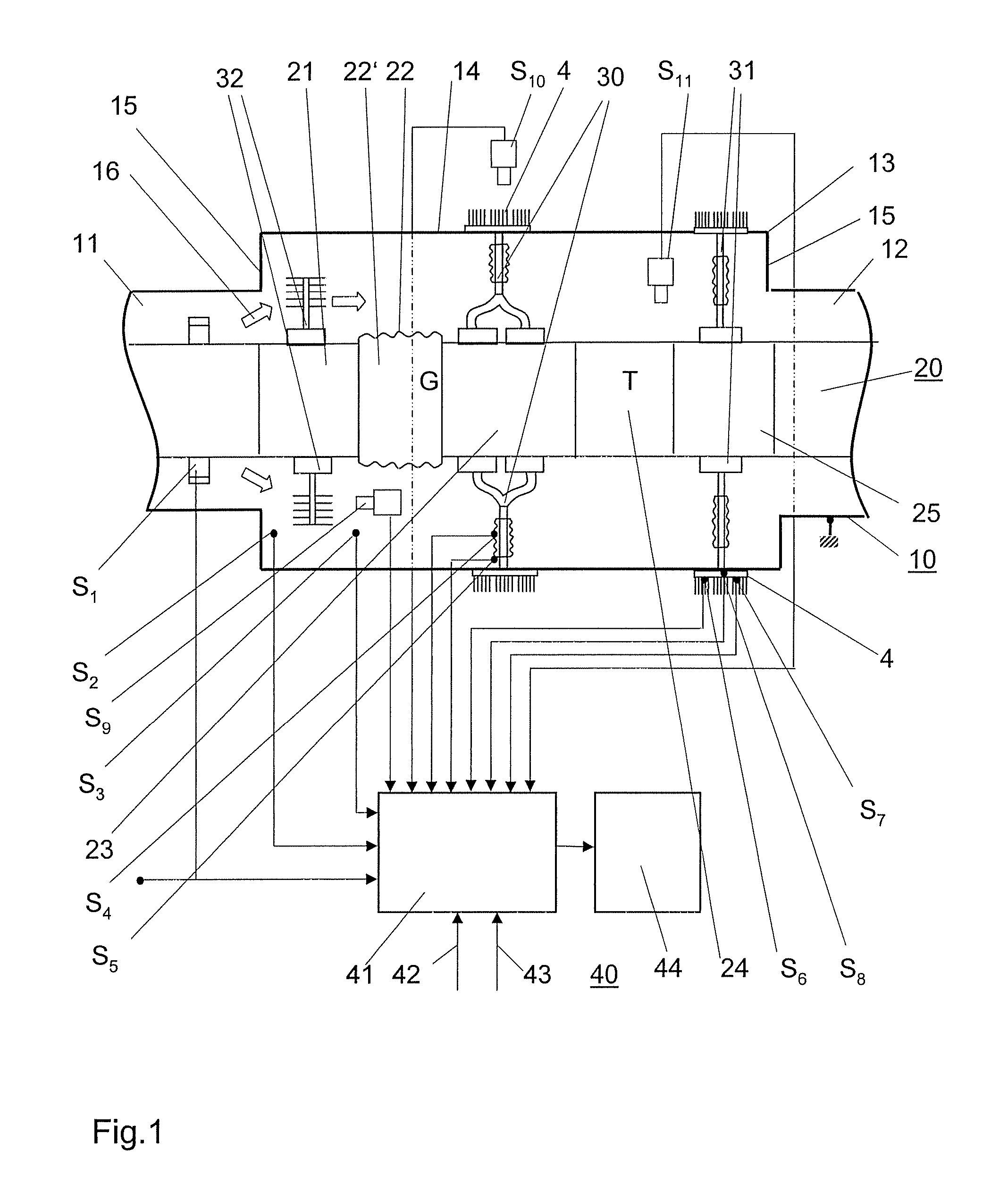
[0006]The disclosure is based on the object of providing an installation of the type mentioned at the outset which is characterized by high operational reliability with high current-carrying capacity and dimensions which are kept small, and of specifying a method for operating this installation.

Problems solved by technology

Furthermore, the superconductor system has a complex pipeline circuit for conducting the cryogenic liquid, to which a condensation unit is coupled which contains a condenser.

Method used


Image

  • Electrical installation with a cooling element and method for operating said installation
  • Electrical installation with a cooling element and method for operating said installation
  • Electrical installation with a cooling element and method for operating said installation

Examples


Embodiment Construction

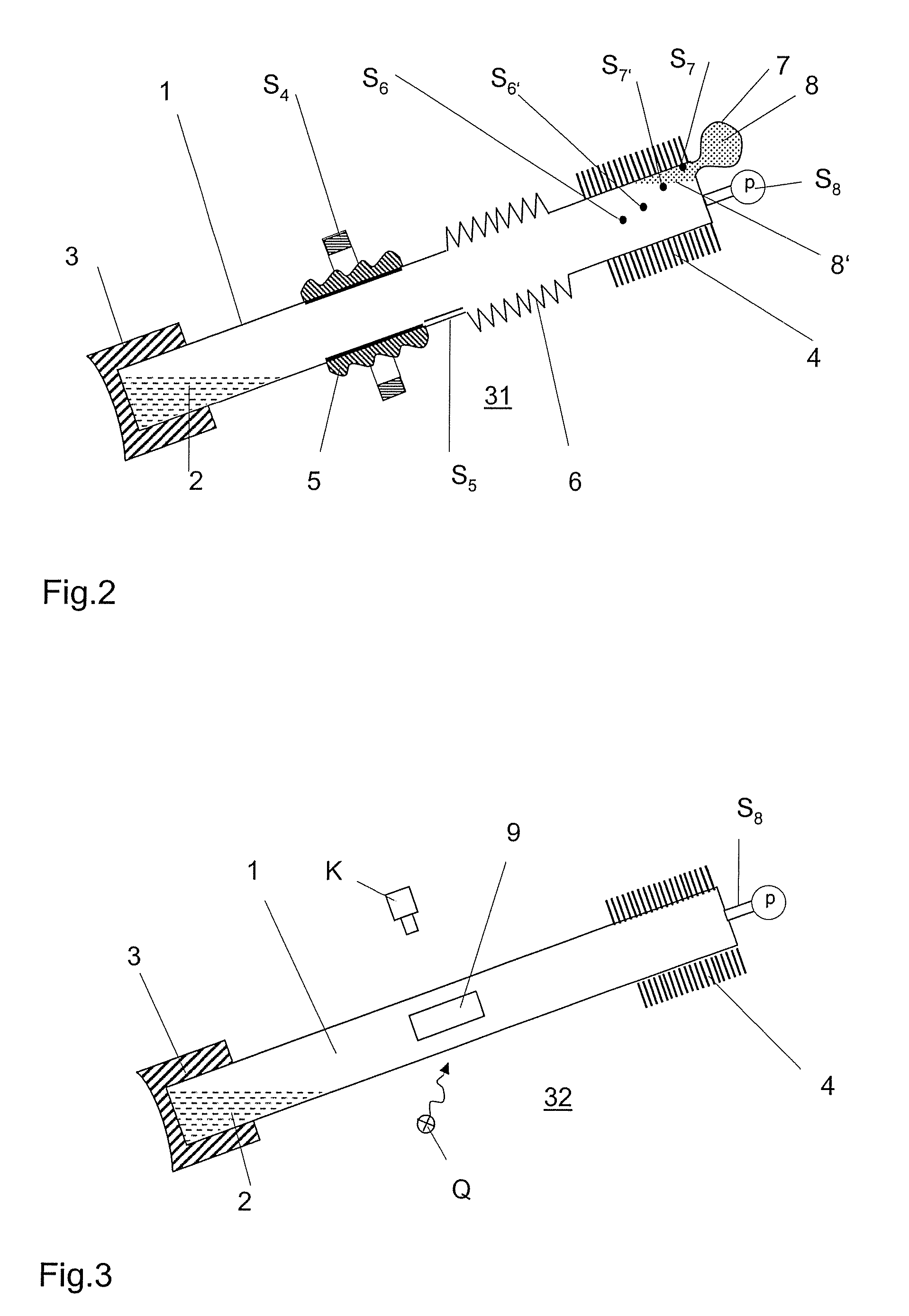
[0013]The installation in accordance with the disclosure contains a monitoring device with at least one sensor for detecting a parameter of the cooling element provided in the installation and with an evaluation unit, which receives output signals from the sensor, for evaluating the output signals and for forming a signal describing the state and / or the functionality of the cooling element. These measures mean that the operator of the installation knows the state and / or the functionality of the cooling element at any time. He can therefore operate the installation with high reliability even when high rated currents are being conducted.

[0014]If the sensor for detecting the temperature and / or the temperature distribution of a condenser is in the form of or arranged as a sensor for detecting the pressure of a working medium in the cooling element or as a sensor for detecting the flow behavior, in particular the throughflow, of the working medium in the cooling element, the state and / or...


PUM

PropertyMeasurementUnit
voltagesaaaaaaaaaa
temperatureaaaaaaaaaa

Abstract

The installation contains a current conductor producing Joulean heat in the operating state, a cooling element and a monitoring device. The cooling element has a condensable working medium and an evaporator, which can be heated by the current conductor of the installation, and a condenser which has been withdrawn from the heating effect of the current conductor. The monitoring device comprises at least one sensor for detecting a parameter of the cooling element and an evaluation unit, which receives output signals from the sensor. In the evaluation unit, the output signals of the sensors are evaluated and a signal describing the state and / or the functionality of the cooling element is formed there. This installation is characterized by high operational reliability with a high current-carrying capacity and dimensions which are kept small.

Description

RELATED APPLICATIONS[0001]This application claims priority under 35 U.S.C. §119 to EP Application 05405396.2 filed in European Patent Office on 23 Jun. 2005, and as a continuation application under 35 U.S.C. §120 to PCT / CH2006 / 000328 filed as an International Application on 16 Jun. 2006 designating the U.S., the entire contents of which are hereby incorporated by reference in their entireties.TECHNICAL FIELD[0002]An electrical installation and a method for operating said installation are disclosed. The installation has a current conductor, which produces Joulean heat during operation of the installation, and a cooling element. The cooling element is used for increasing the rated current-carrying capacity of the installation and contains a condensable working medium and an evaporator, which can be heated by the current conductor of the installation, and a condenser, which has been withdrawn from the heating effect of the current conductor. Such an installation is generally in the for...

Claims


Application Information

Patent Timeline
Patent Type & Authority Patents(United States)
IPC IPC(8): G01K1/00G01K13/00G01K7/00G01K3/00
CPCH02G5/10H01H2009/523H01H2009/526
Inventor KIEFER, JOCHENLAKNER, MARTINMAUROUX, JEAN-CLAUDECHARTOUNI, DANIEL
Owner HITACHI ENERGY LTD
Learn More