Antenna and method of making the same

a technology of antenna and antenna body, applied in the direction of antenna, antenna details, protective material radiating elements, etc., can solve the problems of inability to match the impedance with the feeding portion, resistance increase, and inability to reduce the visibility, etc., and achieve the effect of free-form antenna

Inactive Publication Date: 2010-08-10
HITACHI CABLE
View PDF13 Cites 2 Cited by
  • Summary
  • Abstract
  • Description
  • Claims
  • Application Information

AI Technical Summary

Benefits of technology

[0037]The invention has a beneficial effect that a free shape antenna can be produced by bending a long antenna element formed by sandwiching both sides of line conductors by insulation films without need to worry about short circuiting etc. of the line conductors even when it is bent in a desired shape.

Problems solved by technology

Therefore, the visibility cannot be decreased.
Thus, if the conductor width is not wider than that in case of using the copper wire, the resistance increases and the impedance matching with the feeding portion cannot be obtained.
As a result, the conventional antenna element is not negligible in visual sense since the conductor plate 1 is as large as several mm in width W and about 300 mm in length L. When the antenna is installed at a place such as a window of a vehicle, inside of the vehicle or on the periphery of a television, the visibility in seeing the outside from the vehicle may be reduced, or the design harmony of the entire vehicle may deteriorate.
Further, there are following problems in view of the manufacturing method of the antenna.
In the above drawing method (1), since it is difficult to increase the density, the entire antenna area must be too large in case of using many turns.
Further, when manufacturing an antenna in complex shape, it takes time since the drawing work is not easy, and the cost rises that much.
Thus, if the conductor width is not wider than that in case of using the copper wire, the resistance increases and the impedance matching with the feeding portion cannot be obtained.
Further, the cost is increased due to using the expensive silver paste.
In the above etching method (3), there are many problems on the management of the agents or an environmental point of view since the etching agent is used.
Further, the production speed is reduced since it takes time to dissolve it.

Method used


Image

  • Antenna and method of making the same
  • Antenna and method of making the same
  • Antenna and method of making the same

Examples


example 1

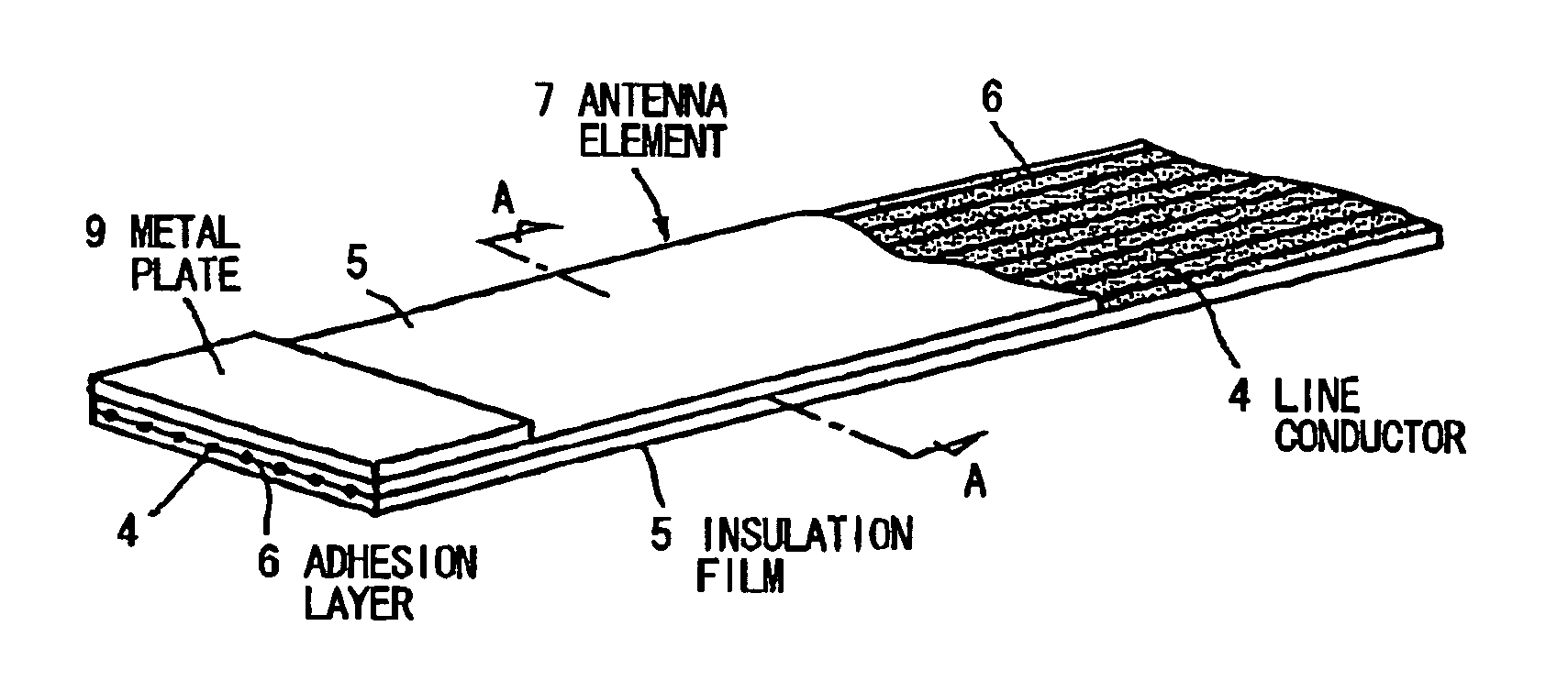
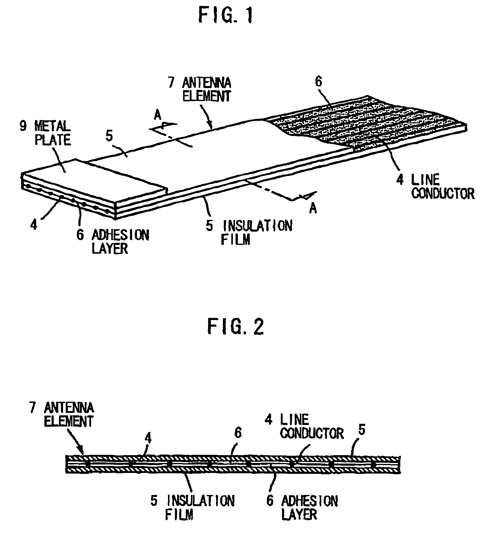
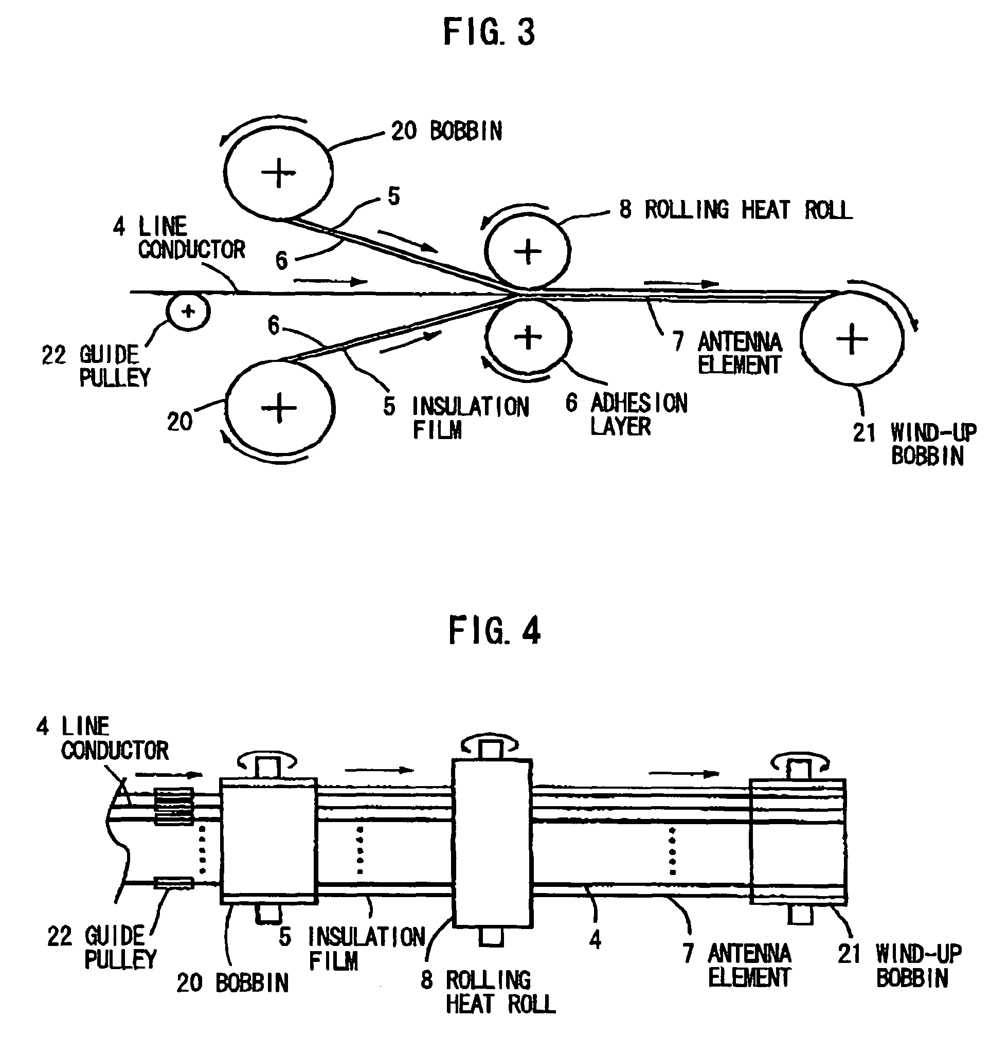
[0076]As shown in FIG. 5, 50 lusterless silver coating copper alloy conductors 10 with a diameter of φ0.02 mm are in parallel arranged at equal intervals of 0.2 mm. Then, the antenna element 7 is formed by conducting the rolling adhesion that the conductors 10 are sandwiched by the transparent insulation films 5 (made of, e.g., polyethylene terephthalate or polycarbonate) with a thickness of 0.015 mm and with the adhesion layer 6 with a thickness of 0.01 mm by using the rolling heat rolls 8 at temperature of 150° C. in accordance with the method explained in FIGS. 3 and 4.

[0077]The antenna element is cut into two strips in equal length, being bent by 90 degrees in midway and forming the dipole antenna 12 to be 300 mm in length L. Then, the dipole antenna 12 is sandwiched by transparent insulating substrates 11 (made of, e.g., polyethylene terephthalate or polycarbonate) with a thickness of 0.015 mm and with an adhesion layer of 0.01 mm while placing a part to be the feeding portion ...

example 2

[0079]As shown in FIG. 6, 50 lusterless silver coating copper alloy conductors 10 with a diameter of φ0.02 mm are in parallel arranged at equal intervals of 0.2 mm. Then, the antenna element 7 is formed by conducting the rolling adhesion that the conductors 10 are sandwiched by the transparent insulation films 5 (made of, e.g., polyethylene terephthalate or polycarbonate) with a thickness of 0.015 mm and with the adhesion layer 6 with a thickness of 0.01 mm by using the rolling heat rolls 8 at temperature of 150° C. in accordance with the method explained in FIGS. 3 and 4.

[0080]The antenna element is cut into a strip with an appropriate length, being bent by 90 degrees in midway to form the rectangular loop antenna 13 to be 300 mm in long side and 50 mm in short side. Then, the loop antenna 13 is sandwiched by transparent insulating substrates 11 (made of, e.g., polyethylene terephthalate or polycarbonate) with a thickness of 0.015 mm and with an adhesion layer of 0.01 mm while plac...

example 3

[0082]As shown in FIG. 7, 50 lusterless silver coating copper alloy conductors 10 with a diameter of φ0.02 mm are in parallel arranged at equal intervals of 0.2 mm. Then, the antenna element 7 is formed by conducting the rolling adhesion that the conductors 10 are sandwiched by the transparent insulation films 5 (made of, e.g., polyethylene terephthalate or polycarbonate) with a thickness of 0.015 mm and with the adhesion layer 6 with a thickness of 0.01 mm by using the rolling heat rolls 8 at temperature of 150° C. in accordance with the method explained in FIGS. 3 and 4.

[0083]The antenna element is cut into a strip with an appropriate length, being bent in midway to form the inverted-triangular loop antenna 14 to be 300 mm in one side. Then, the loop antenna 14 is sandwiched by transparent insulating substrates 11 (made of, e.g., polyethylene terephthalate or polycarbonate) with a thickness of 0.015 mm and with an adhesion layer of 0.01 mm while placing a part to be the feeding po...


PUM


Abstract

An antenna having an antenna element bent in a predetermined shape. The antenna element has a plurality of line conductors that are arranged in parallel and are sandwiched by two insulation films. A method of making an antenna has the steps of: arranging in parallel a plurality of line conductors, each of which having a width of 0.04 mm or less, at intervals of 10 times or more the width of each of the line conductors; discharging continuously the plurality of line conductors such that visibility of the line conductors is reduced; and sandwiching continuously the discharged line conductors by planar transparent insulation films with a sticking or adhesion layer to have an antenna element.

Description

[0001]The present application is based on Japanese patent application No. 2005-274011 filed on Sep. 21, 2005, the entire contents of which are incorporated herein by reference.BACKGROUND OF THE INVENTION[0002]1. Field of the Invention[0003]This invention relates to an antenna for wireless radio communication which receives VHF band and UHF band and, more particularly, to an antenna with decreased visibility of itself and a method of making the antenna.[0004]2. Description of the Related Art[0005]Conventionally, in considering a half-wave dipole antenna as an antenna element to send and receive VHF band (30-300 MHz) and UHF band (300 MHz-3 GHz), a dipole antenna 3 comprises a pair of conductor plates 1, 1, and a feeding portion 2 connected with the conductor plates 1, 1 as shown in FIG. 8.[0006]To decrease the visibility, a film antenna is known that the conductor plate 1 is composed of printing with conductive paste or wire material. Although length L may be varied, the most fundame...

Claims


Application Information

Patent Timeline
Patent Type & Authority Patents(United States)
IPC IPC(8): H01Q1/40
CPCH01Q1/36H01Q7/00H01Q9/285
Inventor HORIKOSHI, TOSHIYUKIKOBAYASHI, MASAHIKOAOYAMA, SEIGIYAMANOBE, HIROSHIMURANO, SHINSUKE
Owner HITACHI CABLE
Why Eureka
Try Eureka