Method of forming a magnetic tunnel junction device

a magnetic tunnel junction and cell technology, applied in the direction of inductance/transformer/magnet manufacturing, magnetic bodies, instruments, etc., can solve the problems of increasing the complexity of wire-trace routing, limited mtj device size, and increasing data density in the x-y direction, so as to reduce parasitic resistance and capacitance, shorten contact distance, and enhance efficiency

Active Publication Date: 2010-08-24
QUALCOMM INC
View PDF5 Cites 23 Cited by
  • Summary
  • Abstract
  • Description
  • Claims
  • Application Information

AI Technical Summary

Benefits of technology

[0008]Another particular advantage is provided in that lateral electrodes provide a shorter contact distance, enhancing efficiency and reducing parasitic resistances and capacitances due to wiring.
[0009]Still another advantage is that the multiple bit MTJ cell can scale with process technology, allowing for multi-bit MTJ cells even as the MTJ cell size decreases.
[0011]Yet another particular advantage is provided in that the MTJ cell can include multiple independent magnetic domains. Each of the multiple independent magnetic domains may be written to or read from without changing data stored at other magnetic domains within the MTJ cell.

Problems solved by technology

However, the size of the MTJ devices is limited by the fabrication process technology.
Unfortunately, such structures store only one bit per cell, so the data density in the X-Y direction is increased at the expense of area in a Z-direction and cost of manufacture.
Further, such structures increase wire-trace routing complexity.

Method used


Image

  • Method of forming a magnetic tunnel junction device
  • Method of forming a magnetic tunnel junction device
  • Method of forming a magnetic tunnel junction device

Examples


Embodiment Construction

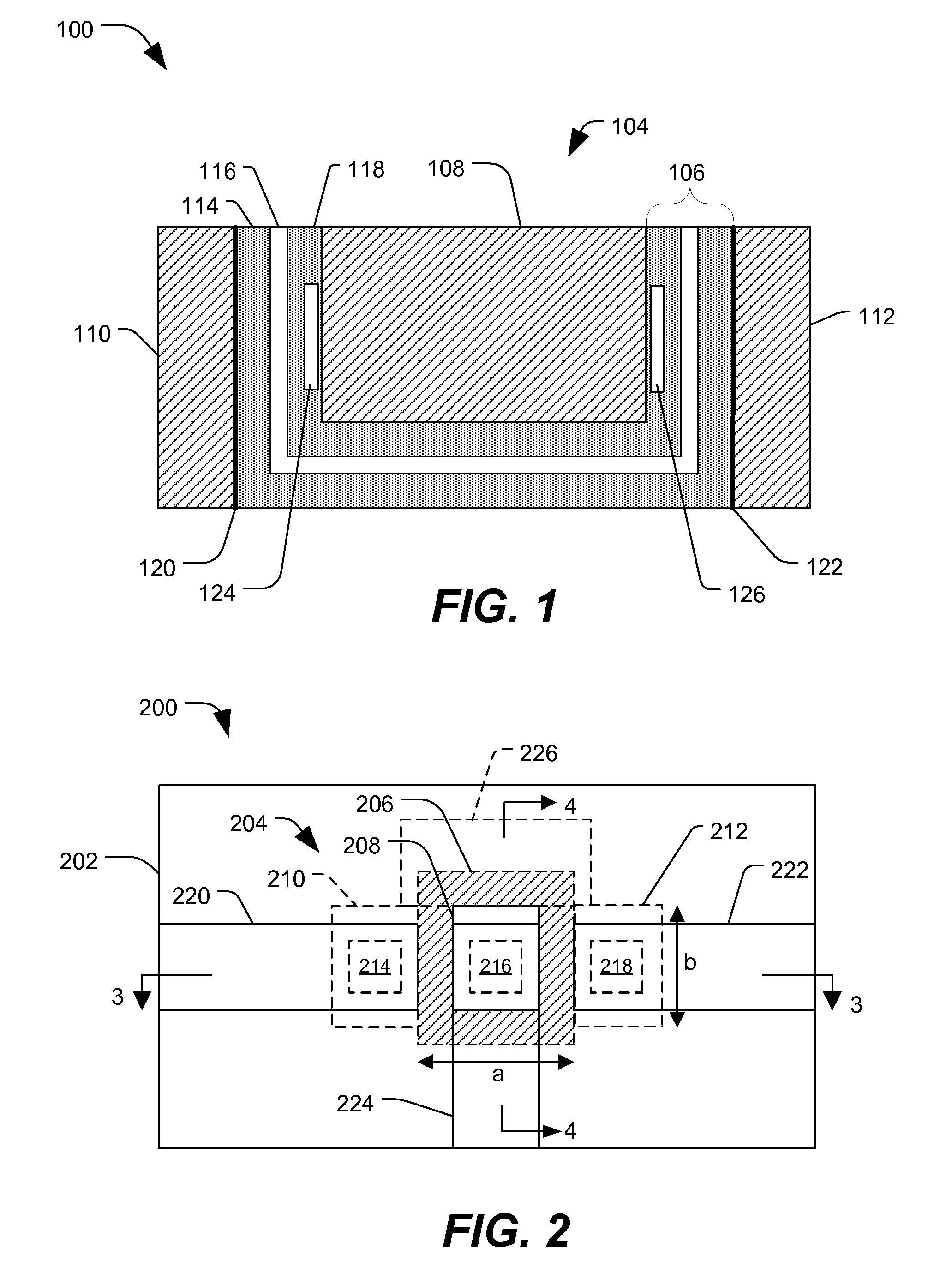
[0055]FIG. 1 is a cross-sectional diagram of a particular illustrative embodiment of a magnetic tunnel junction (MTJ) cell 100 including lateral magnetic domains. The MTJ cell 100 includes a magnetic tunnel junction (MTJ) structure 104 having an MTJ stack 106, a center electrode 108, a first lateral electrode 110, and a second lateral electrode 112. The MTJ stack 106 includes a fixed magnetic layer 114 that carries a magnetic domain having a fixed magnetic orientation, a tunnel barrier layer 116, and a free magnetic layer 118 having a configurable magnetic orientation. The MTJ stack 106 may also include an anti-ferromagnetic (AF) layer (not shown) that pins the fixed magnetic layer 114. The MTJ stack 106 may also include additional layers (not shown). The fixed magnetic layer 114 is coupled to the first lateral electrode 110 via the AF layer at first lateral interface 120 and contacts the second lateral electrode 112 at a second lateral interface 122. It should be understood that th...


PUM


Abstract

A method of manufacturing a magnetic tunnel junction device is disclosed that includes forming a trench in a substrate, depositing a conductive terminal within the trench, and depositing a magnetic tunnel junction (MTJ) structure within the trench. The MTJ structure includes a fixed magnetic layer having a fixed magnetic orientation, a tunnel junction layer, and a free magnetic layer having a configurable magnetic orientation. The fixed magnetic layer is coupled to the conductive terminal along an interface that extends substantially normal to a surface of the substrate. The free magnetic layer that is adjacent to the conductive terminal carries a magnetic domain adapted to store a digital value.

Description

I. FIELD[0001]The present disclosure is generally related to a method of forming a magnetic tunnel junction cell including multiple lateral magnetic domains.II. DESCRIPTION OF RELATED ART[0002]In general, widespread adoption of portable computing devices and wireless communication devices has increased demand for high-density and low-power non-volatile memory. As process technologies have improved, it has become possible to fabricate magneto-resistive random access memory (MRAM) based on magnetic tunnel junction (MTJ) devices. Traditional spin torque tunnel (STT) junction devices are typically formed as flat stack structures. Such devices typically have two-dimensional magnetic tunnel junction (MTJ) cells with a single magnetic domain. An MTJ cell typically includes an anti-ferromagnetic layer (AF), a fixed magnetic layer, a barrier layer (i.e., a tunneling oxide layer), and a free magnetic layer, where a bit value is represented by a magnetic field induced in the free magnetic laye...

Claims


Application Information

Patent Timeline
Patent Type & Authority Patents(United States)
IPC IPC(8): H01L21/00
CPCB82Y25/00B82Y40/00G11C11/16G11C11/5607H01L43/12H01F41/308H01L43/08H01F10/3254H01L27/222G11C2211/5615G11C11/1659G11C11/161H10B61/00H10N50/01H10N50/10
Inventor LI, XIA
Owner QUALCOMM INC
Why Eureka
Try Eureka