Video on demand transaction server

a transaction server and video technology, applied in the field of digital data transmission of video information, can solve the problems of most expensive cable television channels currently available, programming is provided in the “broadcast” mode, programming is missed if the user, etc., and achieve linear increase of hardware resources to implement the video subsystem, linear increase of total input/output load of the video server subsystem, and small (and inexpensive) increments

a transaction server and video technology, applied in the field of digital data transmission of video information, can solve the problems of most expensive cable television channels currently available, programming is provided in the “broadcast” mode, programming is missed if the user, etc., and achieve linear increase of hardware resources to implement the video subsystem, linear increase of total input/output load of the video server subsystem, and small (and inexpensive) increments

US7784079B1Inactive Publication Date: 2010-08-24UNISYS CORP

Image

  • Video on demand transaction server
  • Video on demand transaction server
  • Video on demand transaction server

Examples


Embodiment Construction

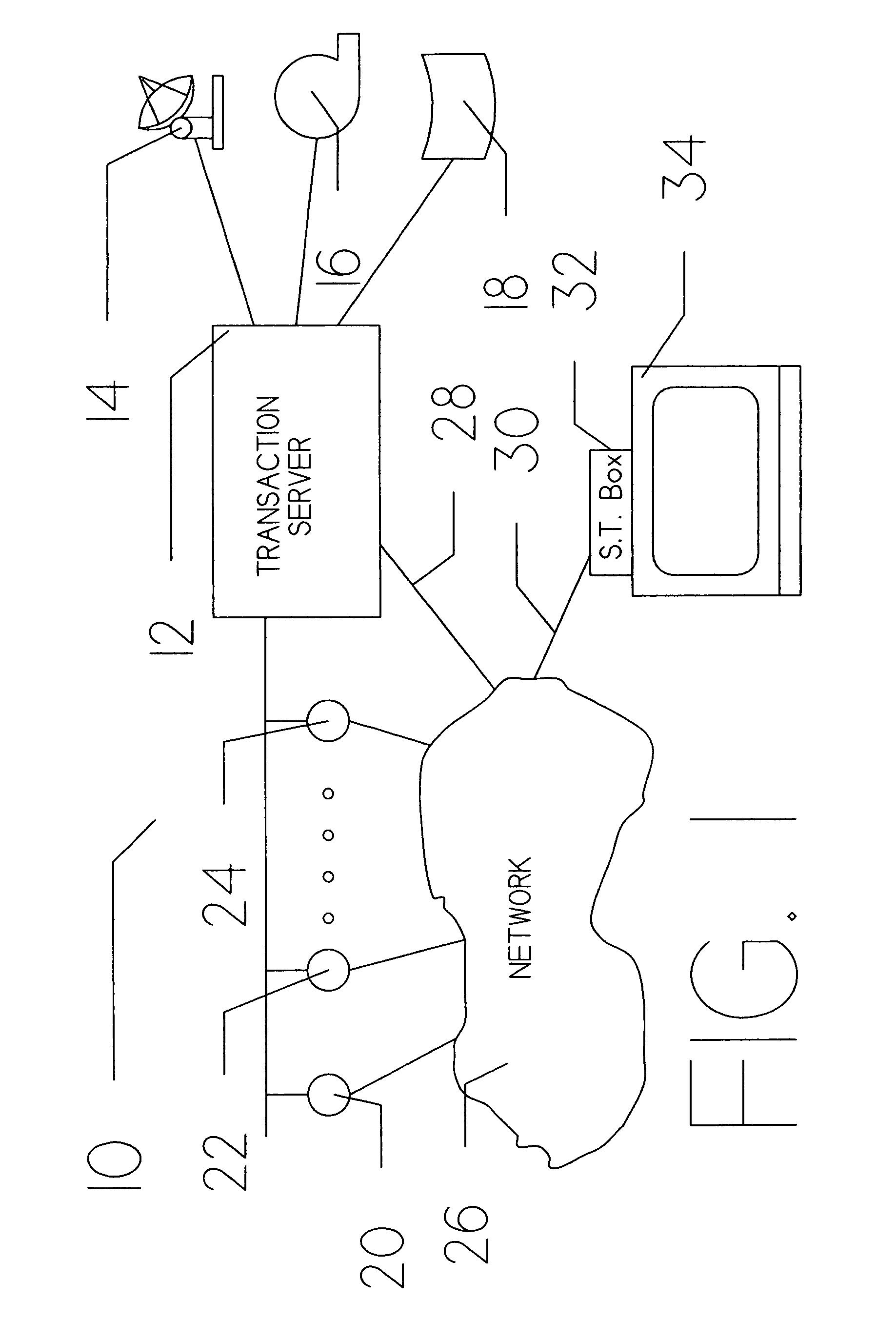
[0040]FIG. 1 is a schematic diagram 10 showing the overall video on demand system of the present invention. A subscribing user (not shown) is positioned adjacent standard television receiver 34. Through this television receiver, the user is capable of viewing video programming material transferred to his location via coaxial cable 30 from network 26 in the fashion currently known in the cable television industry. The interface between coaxial cable 30 and standard television receiver 34 is provided by subscriber box 32, which provides the conversion between MPEG II digitized video format and the analog video signal required by television receiver 34.

[0041]In many respects, subscriber box 32 is similar to the subscriber boxes utilized with existing cable television systems with the slight functional differences described in more detail below. The basic reason for these slight differences is to permit a subscribing user to communicate with transaction server 12 in a two directional ma...


PUM


Abstract

A method of and apparatus for efficiently providing video on demand services to a cable television subscriber. The provider system consists of two major subsystems. The first subsystem, called a video server, streams video to video on demand subscribers through the cable television network. The second subsystem, called the transaction server, performs virtually all remaining provider functions including, security, accounting, storage and spooling of video data, etc. The transaction server preferably uses a large scale mainframe computer. The video server subsystem may be a partitioned portion of same large scale mainframe computer.

Description

CROSS REFERENCE TO CO-PENDING APPLICATIONS[0001]This application is related to commonly assigned and co-pending U.S. patent application Ser. No. 09 / 304,906, filed May 4, 1999, and entitled “Video Server”; U.S. patent application Ser. No. 09 / 304,907, filed May 4, 1999, and entitled “Video on Demand Transaction Gateway”; and U.S. patent application Ser. No. 09 / 400,647, filed Sep. 21, 1999, and entitled “A Web Based Video on Demand Administration Application”, all of which are incorporated by reference.BACKGROUND OF THE INVENTION[0002]1. Field of the Invention[0003]The present invention generally relates to digital data transmission of video information and more particularly to the delivery of user selected video information to subscribing users.[0004]2. Description of the Prior Art[0005]The mass distribution of video programming signals (i.e., television) was originally accomplished primarily by the broadcasting of a very high frequency (i.e., VHF) carrier containing an amplitude modu...

Claims


Application Information

Patent Timeline
24 Aug 2010
Publication
US7784079B1
IPC
H04N7/173
CPC
H04N7/17354; H04N21/218; H04N21/21815; H04N21/254
Inventors
SIPPLE, RALPH E.; MCBREEN, JAMES R.