Apparatus and method of separating

Inactive Publication Date: 2010-08-31
HOSFORD MICHAEL HAYS
View PDF12 Cites 37 Cited by
  • Summary
  • Abstract
  • Description
  • Claims
  • Application Information

AI Technical Summary

Benefits of technology

[0017]The present invention advances tank-based aquaculture by providing a simple, low cost, high efficiency solid waste separator. The invention combines the simplicity of centrifugal-gravitational separation with the practicality of automatic separator cleaning. Low-pressure air from a blower or air pump induces water flow through the separator. The compressed air source is also used to purge accumulated sludge from the separator and to scour internal separator surfaces. Scouring is enhanced with addition of floating granular me

Problems solved by technology

Vessel geometry imperfections result in a certain degree of distortion of the centrifugal flow pattern.
Some other solid waste accumulators typically used for aquaculture recycle systems, including up-flow bead filters (pressurized) and micro-screen filters (non-pressurized), can

Method used


Image

  • Apparatus and method of separating
  • Apparatus and method of separating
  • Apparatus and method of separating

Examples


Embodiment Construction

[0041]In the drawings many details pertaining to fabrication and maintenance utility well-established in the machine construction art and not bearing upon points of novelty are omitted in the interest of descriptive clarity and efficiency.

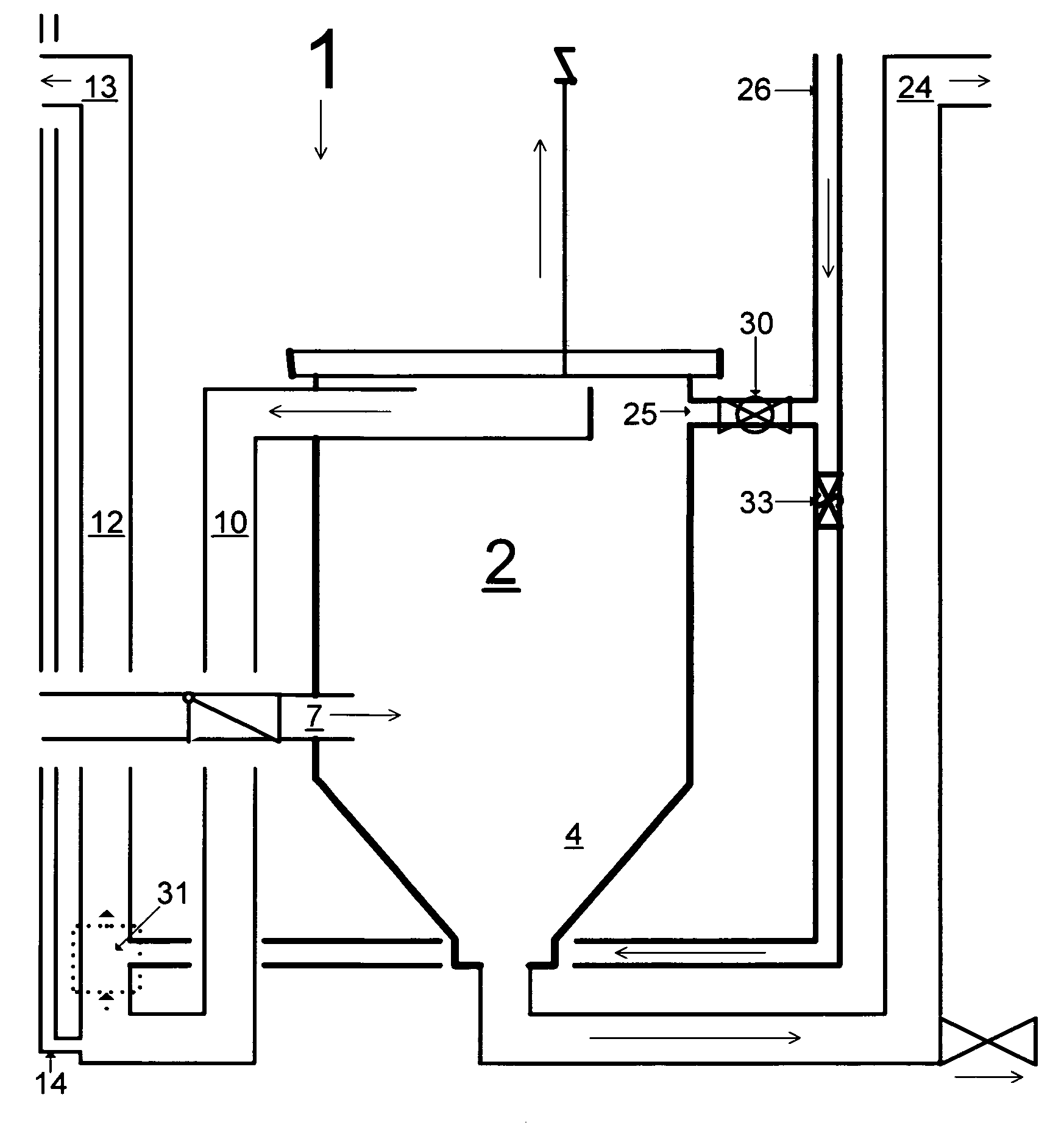
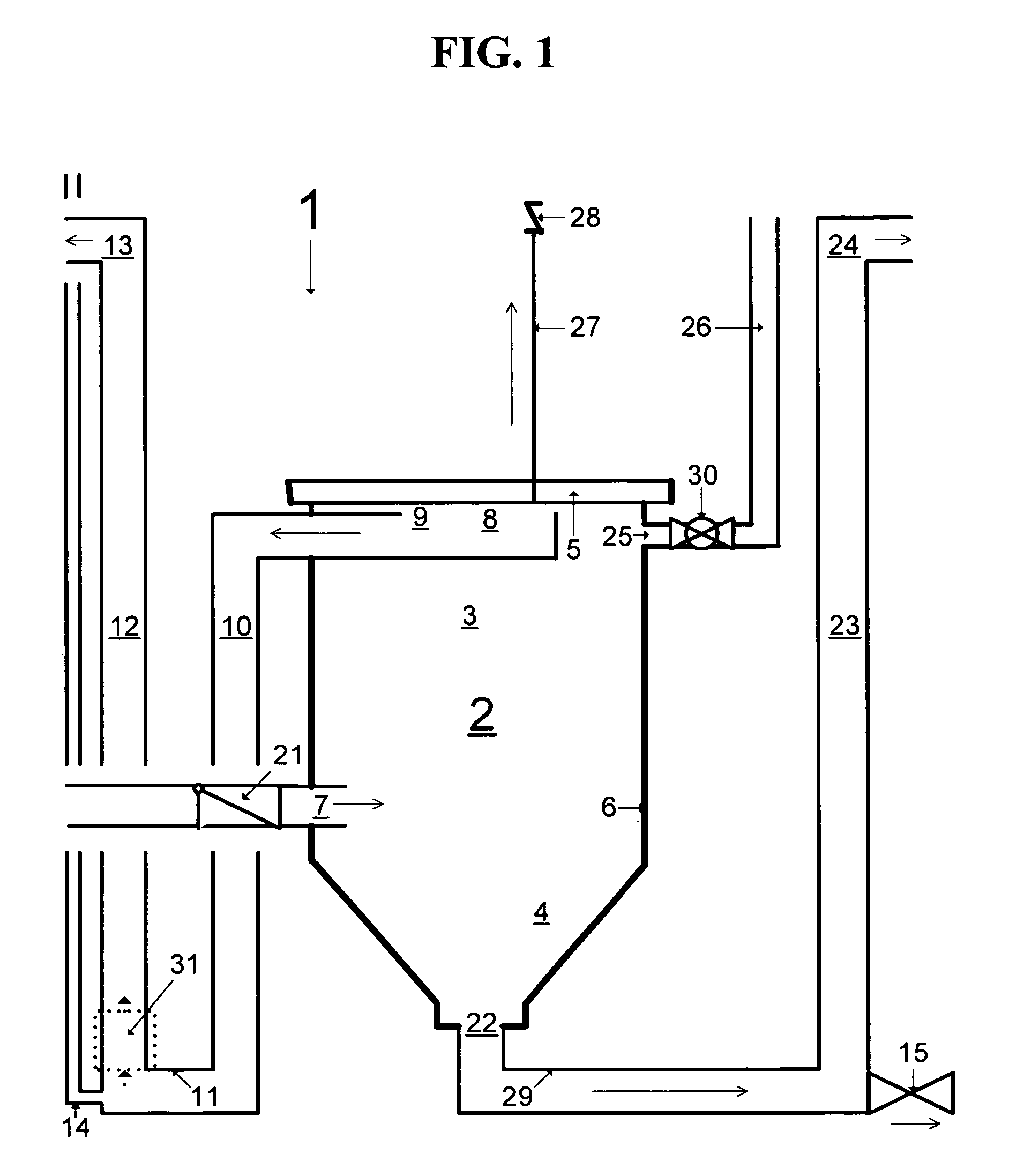
[0042]Referring now to the drawings, there is shown in FIG. 1 an invention, a solid waste particle separating system 1, for treatment of liquid, and more specifically for separation of a solid particle suspension from a liquid flow stream and periodic ejection of the accumulated particles from the liquid environment. The primary separation force of this invention 1 is gravity. Therefore, said particles have a specific gravity greater than the liquid they are suspended in. The invention 1 includes a tank 2 having a removable, gasketed, leak-proof top lid 5, a substantially cylindrical upper portion 3, and a substantially conical lower portion 4. The cylindrical upper portion 3 comprises the particle separation zone, accomplished by centrifugal and g...


PUM

PropertyMeasurementUnit
Pressureaaaaaaaaaa
Flow rateaaaaaaaaaa
Electric potential / voltageaaaaaaaaaa

Abstract

The present invention advances tank-based aquaculture by providing a low cost, high efficiency solid waste separator. The invention combines the simplicity of centrifugal-gravitational separation with the practicality of automatic separator cleaning. Low-pressure air from a blower or air pump induces water flow through the separator. The compressed air source is also used to purge accumulated sludge from the separator and to scour internal separator surfaces. Installation of a captive floating granular media bed within the separator further stabilizes the centrifugal flow pattern, enhances the scouring action during sludge flushing events, and provides substrate for nitrifying bacteria colonization. Separator purging and scouring processes are simply and easily automated with small, low-voltage electric valves and timers. Operational cost-savings are magnified in multiple tank systems where multiple separators are operated by a centralized compressed air system and controller.

Description

CROSS-REFERENCE TO RELATED APPLICATIONS[0001]This application is a continuation-in-part of Ser. No. 12 / 150,881, filed on Apr. 30, 2008, now abandoned titled Apparatus For and Method Of Separating, which claims priority from the provisional patent application Ser. No. 60 / 926,941, filed May 1, 2007, titled Vortex Settling Cone with Pneumatic Sludge Ejection for Separating and Removing Solid Particles from a Liquid Flow Stream.STATEMENT REGARDING FEDERALLY SPONSORED RESEARCH OR DEVELOPMENT[0002]Not ApplicableREFERENCE TO SEQUENCE LISTING, A TABLE, OR A COMPUTER PROGRAM LISTING COMPACT DISC APPENDIX[0003]Not ApplicableBACKGROUND OF THE INVENTION[0004]The present invention has immediate application to the aquaculture industry, and more particularly to an apparatus and method for mechanically separating solid waste particles from a liquid stream and automatically ejecting them from the liquid environment. This invention has immediate application to commercial aquaculture and aquatic resea...

Claims


Application Information

Patent Timeline
IPC IPC(8): B01D21/24B01D21/26
CPCB01D21/0012B01D21/267B01D21/0018B01D21/286C02F1/38C02F3/087C02F3/303C02F3/223C02F2101/16Y02W10/10
Inventor HOSFORD, MICHAEL HAYS
Owner HOSFORD MICHAEL HAYS
Why Eureka
Try Eureka