Method and system for detecting damage in aligned carbon nanotube fiber composites using networks

a carbon nanotube fiber and composite material technology, applied in the direction of resistance/reactance/impedence, instruments, fault locations, etc., can solve the problem that the expected enhancement of composite properties has not been realized

Active Publication Date: 2010-08-31
UNIVERSITY OF DELAWARE
View PDF9 Cites 18 Cited by
  • Summary
  • Abstract
  • Description
  • Claims
  • Application Information

AI Technical Summary

Problems solved by technology

Although exceptional electrical, thermal, and mechanical properties of carbon nanotubes have been researched, expected property enhancements in composites have not been realized.
One of the most significant challenges in improving the properties of nanocomposites based on carbon nanotubes is to obtain a uniform dispersion of nanotubes within the polymer matrix, which is needed to achieve good reinforcement in a composite.

Method used


Image

  • Method and system for detecting damage in aligned carbon nanotube fiber composites using networks
  • Method and system for detecting damage in aligned carbon nanotube fiber composites using networks
  • Method and system for detecting damage in aligned carbon nanotube fiber composites using networks

Examples


example 1

[0116]A micro-scale twin-screw extruder was used to obtain high shear mixing necessary to disentangle CVD-grown multi-walled nanotubes and to disperse them uniformly in a polystyrene thermoplastic matrix.

[0117]The polymer melt was then extruded through a rectangular die and drawn under tension before solidification. The process of extruding the nanocomposite through the die and subsequent drawing resulted in a continuous ribbon of aligned nanocomposites. These aligned nanocomposite films could be subsequently laminated using traditional composites processing techniques such as autoclave or tape placement techniques to create macro-scale aligned nanocomposites.

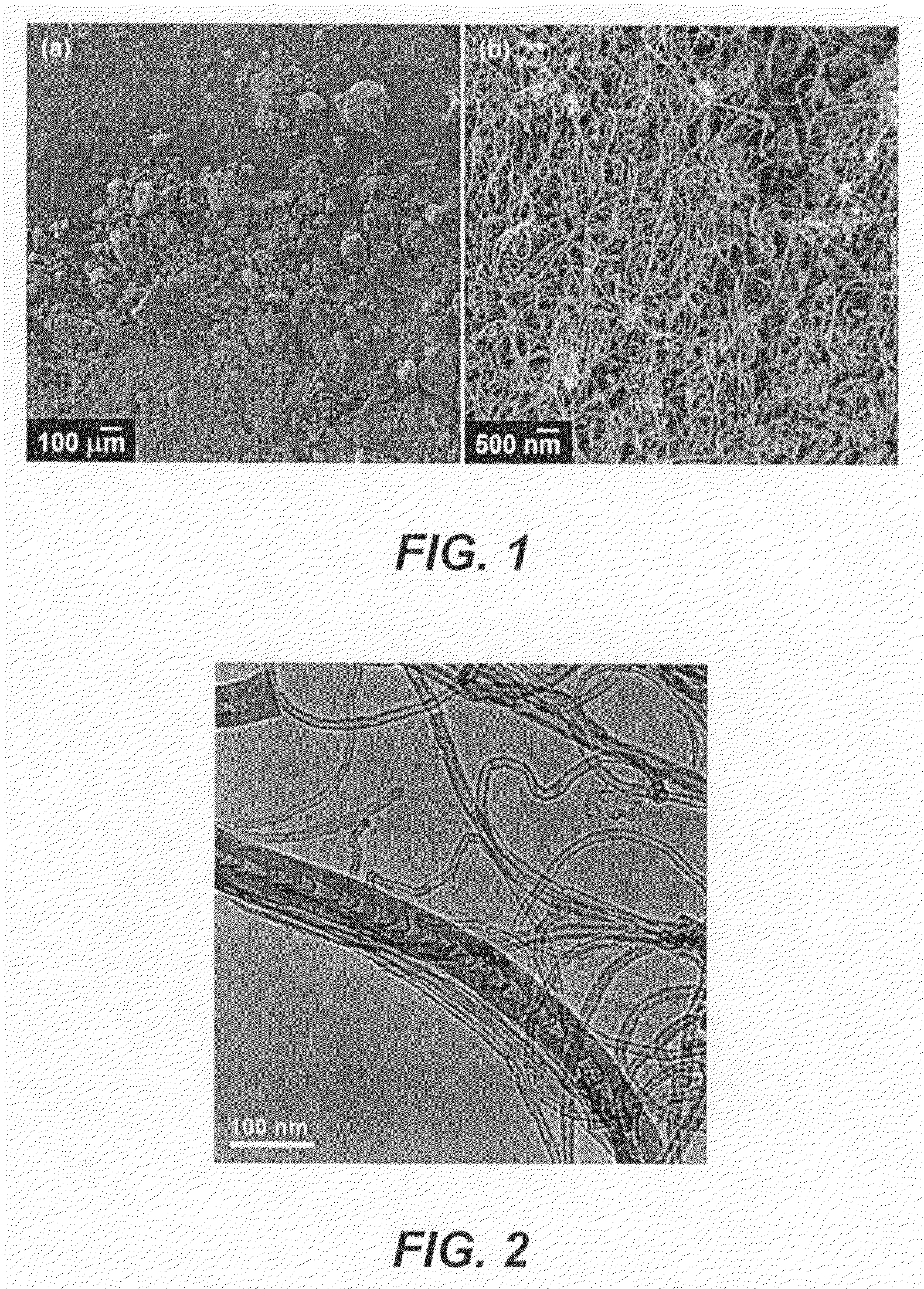
[0118]The structure of the films was investigated using electron microscopy and the tensile behavior characterized using a dynamic mechanical analyzer.

[0119]The micro-scale twin-screw extruder can be used to achieve dispersion of multi-walled carbon nanotubes in a thermoplastic / thermoset polymer matrix. In the present examples ...

example 2

[0122]In another embodiment, carbon nanotubes were first dispersed in a solvent and placed in a sonicator bath for mixing. The mixture was sonicated for at least 15 minutes. Under continued sonication, a polymer compatible with the solvent was slowly added to the nanotube / solvent mixture until completely dissolved. The nanotube / solvent / polymer was sonicated for at least 15 minutes until enough solvent evaporated to form a viscous mixture. The solvent was then allowed to evaporate and the remaining nanotube / polymer mixture was dried in a vacuum oven.

[0123]After drying, the nanotube / polymer solids were fed into a twin-screw extruder and the temperature, mixing rate, and mixing time were specified to obtain high shear stresses in the extruder flow. The molten polymer was then extruded through a die and drawn under tension to form a continuous ribbon of the polymer / nanotube mixture.

[0124]Resulting electron microscopy shows both dispersion of the carbon nanotubes and alignment in a prima...

example 3

[0127]To disperse CVD-grown multi-walled carbon nanotubes in a polystyrene matrix, a micro-scale twin-screw extruder (DACA Instruments—Goleta, Calif.) was used to obtain the high shear mixing necessary to disentangle and disperse the nanotubes.

[0128]To obtain tight control over the weight fraction of nanotubes within the polymer and minimize exposure to nanotubes that become airborne, 3.5 g of polystyrene (280 K Mw—Scientific Polymer, Inc) was dissolved in tetrahydrofuran (THF) and mixed with 184.2 mg of nanotube powder.

[0129]The solution was cast in a petri dish and sonicated as the solvent was evaporated. The purpose of sonication was not to enhance the nano-scale dispersion of nanotubes within the polymer but rather to assure the nanotubes were dispersed on the microscale so that they are encapsulated within the polymer after evaporation of the solvent.

[0130]After drying, the mixture of nanotubes and polymer was then fed into the extruder, which was pre-heated to 155° C., and the...


PUM

PropertyMeasurementUnit
elastic moduliaaaaaaaaaa
diameter distributionaaaaaaaaaa

Abstract

Methods and structural defect detectors for detecting a structural defect in composites are presented. An exemplary method includes forming a nanocomposite including a plurality of nanotubes mechanically aligned in a principal direction within a polymer matrix. A voltage is applied to the nanocomposite and a resistance of the nanocomposite is measured using the applied voltage to detect the structural defect. An exemplary structural defect detector includes a nanocomposite including a plurality of mechanically aligned nanotubes within the polymer matrix, electrodes coupled to the nanocomposite, a voltage source for applying a voltage to the electrodes, and a resistance detector for measuring a resistance of the nanocomposite that allows identification of a structural defect. The plurality of nanotubes form a conducting percolating network of sensors.

Description

CROSS REFERENCE TO RELATED APPLICATIONS[0001]This application is a continuation in part of U.S. Nonprovisional application Ser. No. 10 / 567,349 file Mar. 28, 2007 which is a National Stage Entry of International Application No. PCT / US04 / 25272 filed Aug. 6, 2004 and which is related to and claims the benefit of U.S. Provisional Application 60 / 492,904, filed Aug. 6, 2003, the entire contents of which are hereby incorporated by reference.STATEMENT REGARDING FEDERALLY SPONSORED RESEARCH[0002]The U.S. Air Force Office of Scientific Research funded this research under contract number F49620-02-1-0328.FIELD OF THE INVENTION[0003]The present invention relates to the technical field of carbon nanotube-reinforced polymer composites and, in particular, to the detection of structural defects in the polymer matrix of the composite.BACKGROUND[0004]The exceptional mechanical and physical properties observed for carbon nanotubes has stimulated the development of nanotube-based composite materials. S...

Claims


Application Information

Patent Timeline
Patent Type & Authority Patents(United States)
IPC IPC(8): G01R31/08B29C48/405B29C48/525
CPCB29C47/0004B29C47/40B29C55/00B82Y15/00B82Y30/00C08K3/04C08K7/24B29C47/0021B29C47/38B29C47/402B29C47/6012B29K2105/06B29K2105/162B29C48/022B29C48/08B29C48/395B29C48/405B29C48/525B29C48/402
Inventor THOSTENSON, ERIK T.CHOU, TSU-WEI
Owner UNIVERSITY OF DELAWARE
Why Eureka
Try Eureka