
High speed digital signaling apparatus and method using reflected signals to increase total delivered current

a digital signaling and reflected signal technology, applied in the direction of logic circuit coupling/interface arrangement, pulse technique, instruments, etc., can solve the problems of degrading signal integrity, undesirable signal reflection in prior art designs, and relatively slow compared write transducer magnetic switching speed

Active Publication Date: 2010-08-31
WESTERN DIGITAL TECH INC
View PDF21 Cites 6 Cited by
  • Summary
  • Abstract
  • Description
  • Claims
  • Application Information

AI Technical Summary

Benefits of technology

The patent describes an improved design for a low power digital signaling system that uses signal reflections in transmission lines to provide additional current to a receiver. By using dynamic termination controls, the system can exploit the reflections to enhance the total current available to drive the receiver without increasing power dissipation in the write driver. The system can be used in high-speed digital signaling systems where pre-emphasis of the transmitted signal is desired or required to compensate for low pass filtering response of the transmission line interconnect. The invention allows for faster transition times in written data and reduces the required coil current, resulting in lower power dissipation in the write driver. The system uses source-side termination and termination controls to generate signal reflections that constructively add to direct signals to enhance the total current available to drive the receiver. The invention also allows for balanced signals in the differential excitation from the write driver to the write head. The optimal overshoot amplitude and overshoot duration can be pre-programmed or found through an optimization procedure.

Problems solved by technology

In addition, the write transducer's magnetic switching speed can be relatively slow compared to the desired data rate, which requires a boost or overshoot during write signal reversals.
If the write driver's impedance is significantly mismatched with the characteristic impedance of the transmission line, undesirable signal reflections can occur in prior art designs.
The reflected signal can interfere with the transmitted signal, causing distortion and degrading signal integrity.
However, if the signal were to be reflected by the output circuit, this could interfere with the detection of switching transitions.
Data rates in commercial hard disks are expected to move above 3 Gbps in the next few years, and the continued increase in data rates pose a power and heat challenge for designers.

Method used


Image

  • High speed digital signaling apparatus and method using reflected signals to increase total delivered current
  • High speed digital signaling apparatus and method using reflected signals to increase total delivered current
  • High speed digital signaling apparatus and method using reflected signals to increase total delivered current

Examples


Embodiment Construction

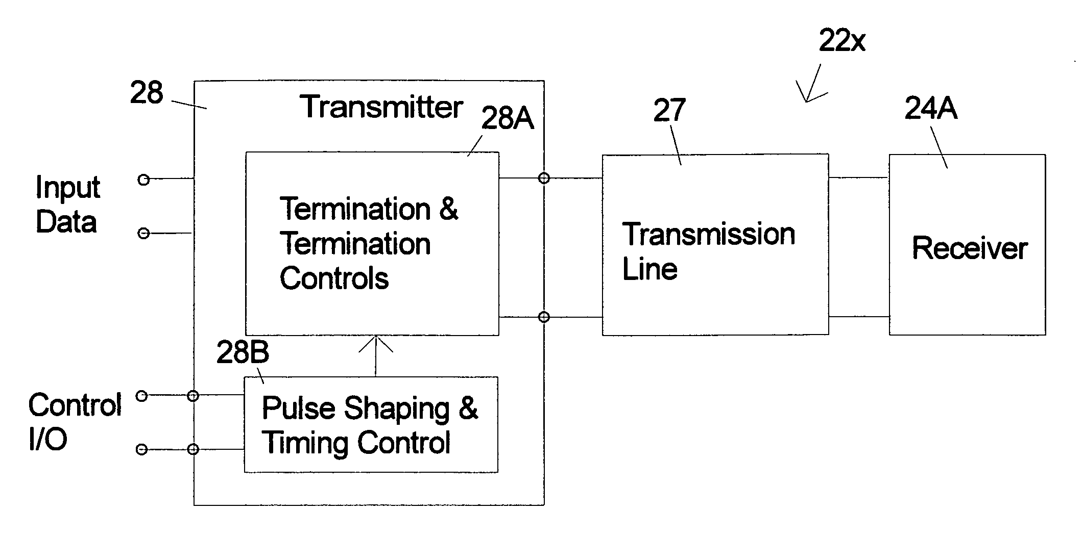
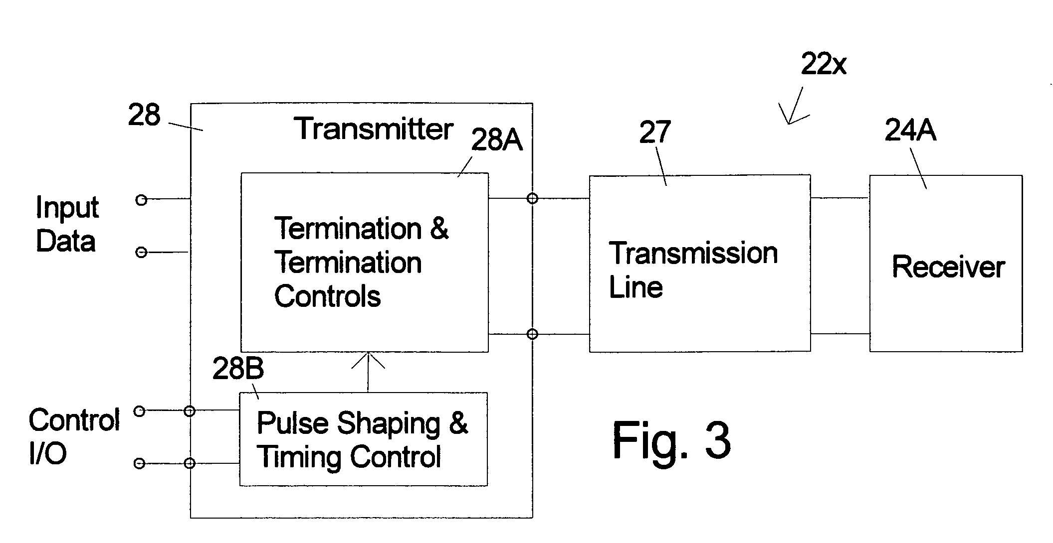
[0034]FIG. 3 is a simplified schematic description of a signaling system 22x embodiment of the invention using a transmitter 28 that includes source-side termination and termination controls 28A and pulse shaping and time control 28B. The transmitter 28 is connected to receiver 24A by transmission line 27. The decisions on the control of the source-side termination are made inside the transmitter based on the input data to be written and the I / O controls supplied by the read / write channel. In alternative embodiments of the invention, the overshoot amplitude, duration and the current level the system returns to after the overshoot are parameters that can be preprogrammed into the system, can be defined (programmed) by the user at any time, or can be determined by means of optimization algorithms that find the optimal value for those parameters to minimize, for instance, bit error rate (BER) in the received data by the receiver or in the read data from the disk. In the particular embo...


PUM


Abstract

A signaling apparatus and method are described that use reflected signals to increase the total current delivered to a receiver. Dynamic source-side transmission line termination control is employed to generate reflected signals that constructively add to a nonreflected signal to enhance the signal at the receiver. Switching controls selectively connect and disconnect the transmission line source-side termination resistors to either provide signal termination or remove it. Driver designs using either voltage or current sources for use in signaling systems (including, for example, magnetic storage devices with inductive coil based write heads) are described.

Description

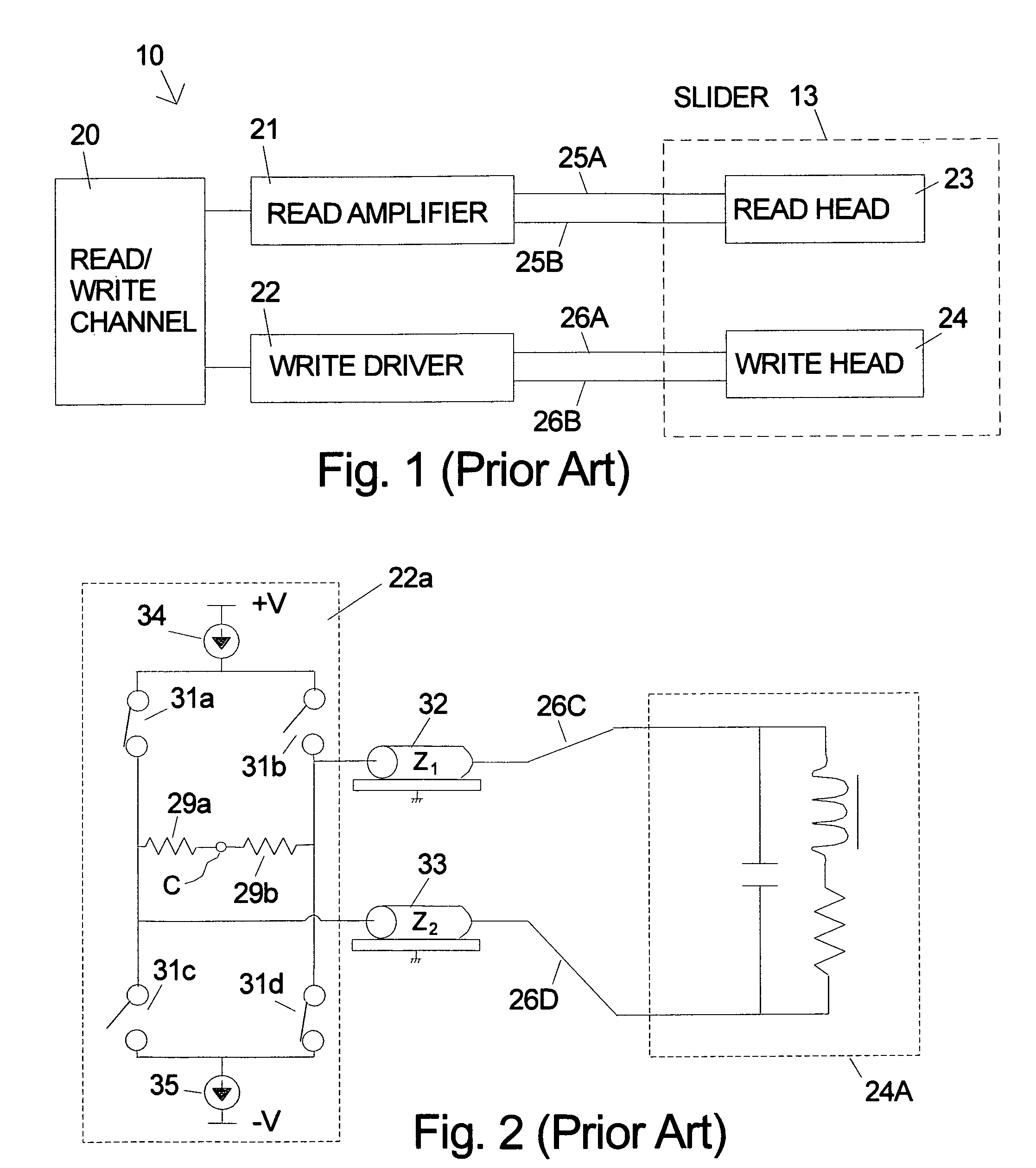
FIELD OF THE INVENTION[0001]This invention relates to high speed signaling systems using pre-emphasis of the transmitted signal.BACKGROUND[0002]There are many applications in which it is desirable to enhance transition speed of a signal that is transmitted on a transmission line to a transducer or receiver. It is also important to provide this enhancement while expending the least amount of power, or no extra power at all. In the following, the particular example of a current delivered the write coil of a magnetic data storage device will be used as an illustrative example, which also includes the additional challenge of maintaining the write current level in the coil while lowering power dissipation in the system. The current invention however has broader application as will be appreciated by those of skill in the art.[0003]Magnetic data storage devices include front-end circuits 10 (see FIG. 1) that read and write the data to the storage media, such as used in hard disk drive (HDD...

Claims


Application Information

Patent Timeline
Patent Type & Authority Patents(United States)
IPC IPC(8): H03K17/16
CPCG11B5/022G11B5/09G11B2005/0013H03K19/0185
Inventor CONTRERAS, JOHN THOMASFRANCA-NETO, LUIZ
Owner WESTERN DIGITAL TECH INC
Learn More