Broad spectrum light source

a light source and broad spectrum technology, applied in the field of light sources, can solve the problems of difficult fabrication, inability to move the zero dispersion wavelength, etc., and achieve the effect of compact and inexpensiv

Active Publication Date: 2010-08-31
NKT PHOTONICS
View PDF8 Cites 55 Cited by
  • Summary
  • Abstract
  • Description
  • Claims
  • Application Information

AI Technical Summary

Benefits of technology

[0010]An object of the invention is to provide a relatively compact and inexpensive source of light of wavelengths spread over a broad spectrum.
[0013]Microchip lasers are significantly cheaper and more compact than mainframe lasers such as Kr-ion lasers.

Problems solved by technology

It is not possible, however, to move the zero dispersion wavelength, λ0, of a silica step-index single-mode optical fibre to wavelengths shorter than 1270 nm, the zero dispersion wavelength of bulk silica.
Though these fibres are typically not strictly single-mode, higher order modes are difficult to excite and are also not coupled to the fundamental mode by normal bending, so the fibres may be used as if single mode.
Prior-art systems utilising frequency-doubled microchip lasers operating at 532 nm produce pulses that propagate in higher-order modes of their micro-structured fibres; to propagate in the fundamental mode at that wavelength, the core of the micro-structured fibre would need to be less than 1 micron in diameter, which is difficult to fabricate.

Method used


Image

  • Broad spectrum light source
  • Broad spectrum light source
  • Broad spectrum light source

Examples


case b

) λpump≦λ0

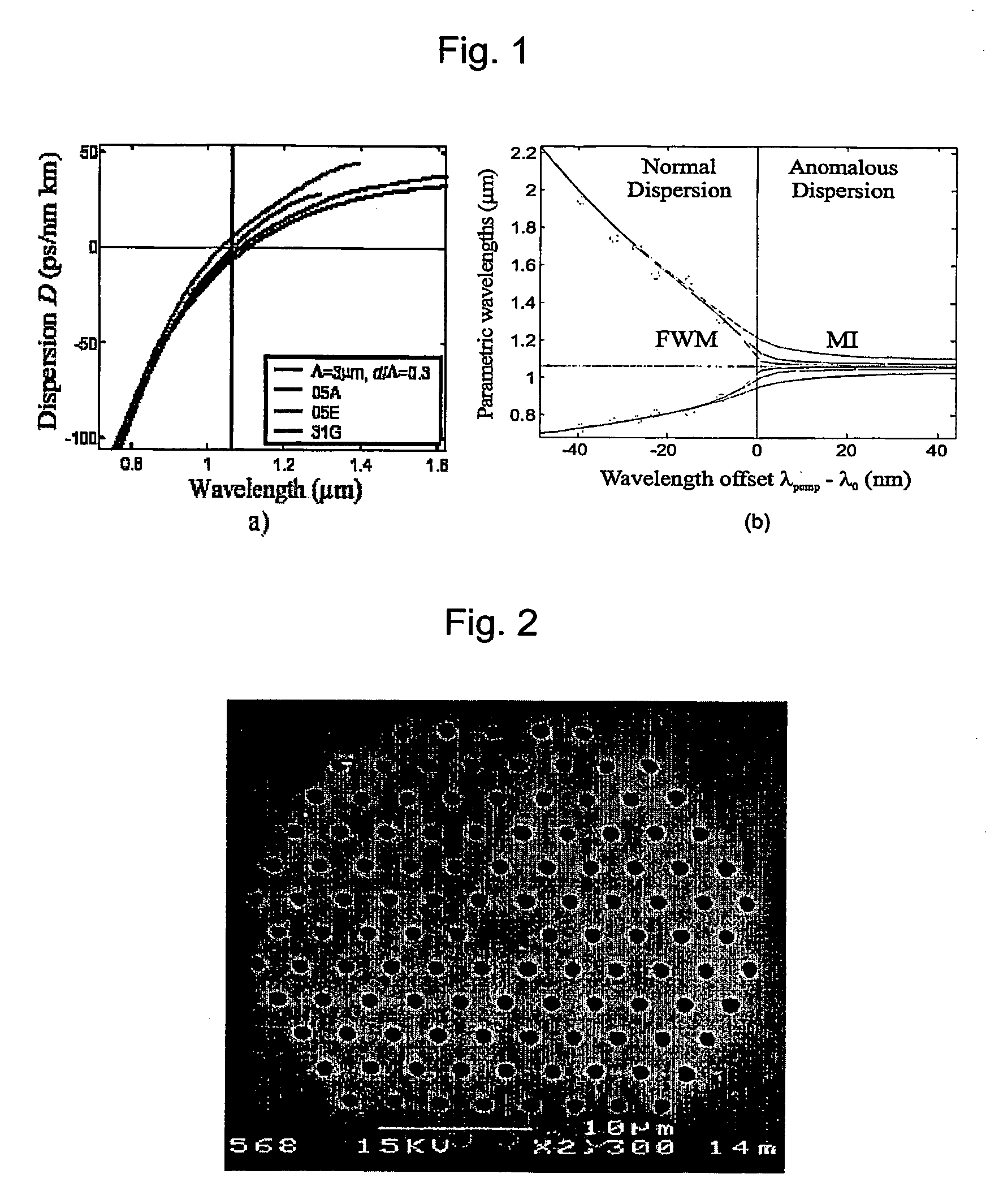
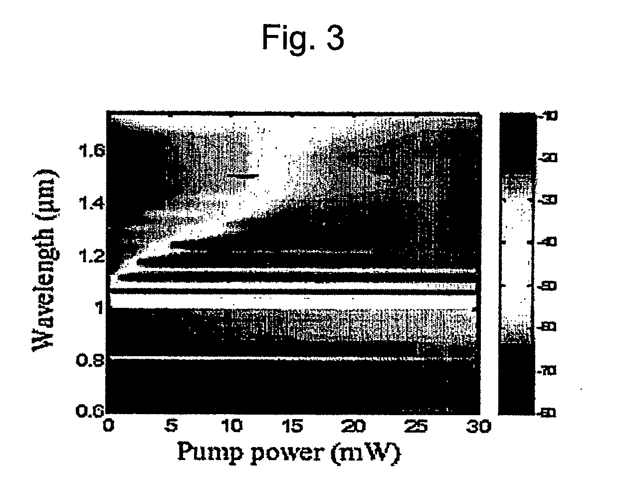
[0063]PCF L has a measured zero dispersion wavelength λ0=1069 nm. The pump wavelength offset is small, −5 nm, which lies in the region where there is phase matching of widely spaced wavelengths, with little power dependence (FWM, the left half of FIG. 1(b). The dispersion at the pump wavelength is also small, just −1 ps / nm km. The evolution of the measured output spectrum with input power is shown in FIG. 4(a) for 6 m of this fibre. At low power, two distinct parametric wavelengths are generated at 895 and 1315 nm, equally spaced in energy about the pump wavelength. This is as expected from phase matching calculations. As the pump power is increased further, there is spectral broadening about the pump, signal and idler wavelengths. For other PCFs, A-N, with the pump offset from λ0 by up to −40 nm, similar parametric generation is seen, with signal wavelengths ranging from 686 nm to 975 nm, and idler wavelengths ranging from 1168 nm to beyond 1900 nm (table 1, FIG. 5(a)).

[...

case c

) λpump>λ0

[0067]PCF P has a measured zero dispersion wavelength λ0=1039 nm. The pump wavelength offset is +25 nm, which lies in the region where there is power-dependent phase matching of closely spaced wavelengths (MI, the right half of FIG. 1(b)). The dispersion at the pump wavelength is +5 ps / nm km. The evolution of the measured output spectra for 1 m, 3 m, 20 m and 100 m of this fibre with input power is shown in FIG. 7. For short 1 m and 3 m lengths, the symmetrical MI peaks are clearly visible dose on either side of the pump wavelength. At low power (5-7 mW) there is a shift of the generated MI wavelengths with input power as expected from equation (1), but once there is significant power in the MI peaks the wavelengths become fixed through saturation. For long 20 m and 100 m lengths of fibre, MI is only visible at the very lowest powers, <2 mW. The wavelengths generated are much closer to the pump (scarcely separated from the pump for 100 m), as expected from the lower pump ...


PUM

PropertyMeasurementUnit
wavelengthsaaaaaaaaaa
diameteraaaaaaaaaa
fundamental wavelengthaaaaaaaaaa

Abstract

The light includes a laser (4), which operates at or near its fundamental wavelength and produces pulses of a duration longer than 0.5 ns, and a micro-structured optical fibre (9) arranged to guide the pulses, wherein the light is generated by the pulses in the fibre (9). The light source may e.g. be useful in applications such as spectral testing of fibre components and spectral analysis of chemical and biological samples.

Description

TECHNICAL FIELD[0001]This invention relates to the field of light sources and in particular to sources of light of wavelengths extending across a broad spectrum of hundreds of nanometers.BACKGROUND ART[0002]There has been much interest in recent years in nonlinear interactions in optical fibres. The low nonlinearity of, for example, silica glass is offset by long interaction lengths and high power density in fibre to yield spectacular nonlinear effects. For most nonlinear processes the physical fibre length can be made longer than the effective interaction length, which is governed by phase matching, pulse broadening, walk-off and attenuation. In particular, the fibre dispersion plays a key role in short pulse propagation and in phase matching conditions for nonlinear processes.[0003]In the spectral region beyond 1300 nm, where the material dispersion of silica glass is itself anomalous, fibres can be designed and made to have a modal dispersion which is normal or anomalous, with a ...

Claims


Application Information

Patent Timeline
Patent Type & Authority Patents(United States)
IPC IPC(8): H01S3/30G02F1/35G02F1/365G02F1/39
CPCG02F1/365G02F1/353G02F1/395G02F2001/3528G02F2201/02G02F2202/32H01S3/0627G02F1/3528
Inventor WADSWORTH, WILLIAM
Owner NKT PHOTONICS
Why Eureka
Try Eureka