Vial assembly and method for reducing nosocomial infections

a nosocomial infection and assembly method technology, applied in the field of vacuum break system, can solve the problems of air in contact with medicinal fluid, little recognition, contaminating iv fluid, and affecting the quality of the air in the bag, so as to achieve uniform and even bag collapse

Inactive Publication Date: 2010-09-07
YANDELL MARION E
View PDF31 Cites 55 Cited by
  • Summary
  • Abstract
  • Description
  • Claims
  • Application Information

AI Technical Summary

Benefits of technology

[0014]In each of the several embodiments of the inventive vial assembly having the vacuum-break feature which permits withdrawal of medicinal fluid from the vial without prior pressure-zation, the medicinal fluid is kept separate from the air, thus eliminating contamination and the need for the USP 797 standards under ISO Class 5 environment and procedures. The isolation of the medicinal fluid from the air is necessary to fill the void in the vial left when fluid is removed and so that in fact the fluid can be removed. Without volume compensation, vacuum lock would occur.
[0015]In all embodiments, pre-pressurization of the vial by hypodermic is both unnecessary and to be avoided. The hypodermic can be filled with the bottle or vial upright or in the standard, inverted-fill position. In all embodiments the principles are the same, an expanding bladder, expanding bellows or sliding diaphragm moves in the vial as medicinal fluid is withdrawn to compensate for the volume of fluid withdrawn. No vacuum lock occurs as the filled volume is reduced by withdrawal of fluid, and no contaminated air comes into contact with the medicinal fluid.
[0016]The first, preferred embodiment employs a special needle sheath assembly mounted centrally in a planar annulus or ring that is gripped by the depending collar of the vial stopper. The central opening communicates with a conical funnel, the bottom of which communicates with a perforated sleeve. The bottom end of the sleeve is closed and of thickness to prevent piercing by the needle. This needle sheath permits introduction of the needle through the elastomeric plug, but the needle will not pierce the bladder as the apertures in the sleeve are laterally oriented and the lower end is robust enough to prevent being pierced by the sharp tip of the needle. In addition, the preferred configuration of the needle sheath includes a sleeve long enough to provide free space between the end of the needle and the closed end of the sheath even when the hypodermic is pushed deeply into the vial, even far enough th

Problems solved by technology

In addition, special medical fluids are introduced by hypodermics into IV lines (typically by Y-tube connectors or into the bags themselves), thus contaminating the IV fluid.
While open medicine bottles have been abandoned as unsanitary for over 50 years, there has been little, if any, recognition of the introduction, at the time of filling of the hypodermic, of microbes in the ambient air introduced into closed vials via the s

Method used


Image

  • Vial assembly and method for reducing nosocomial infections
  • Vial assembly and method for reducing nosocomial infections
  • Vial assembly and method for reducing nosocomial infections

Examples


first embodiment

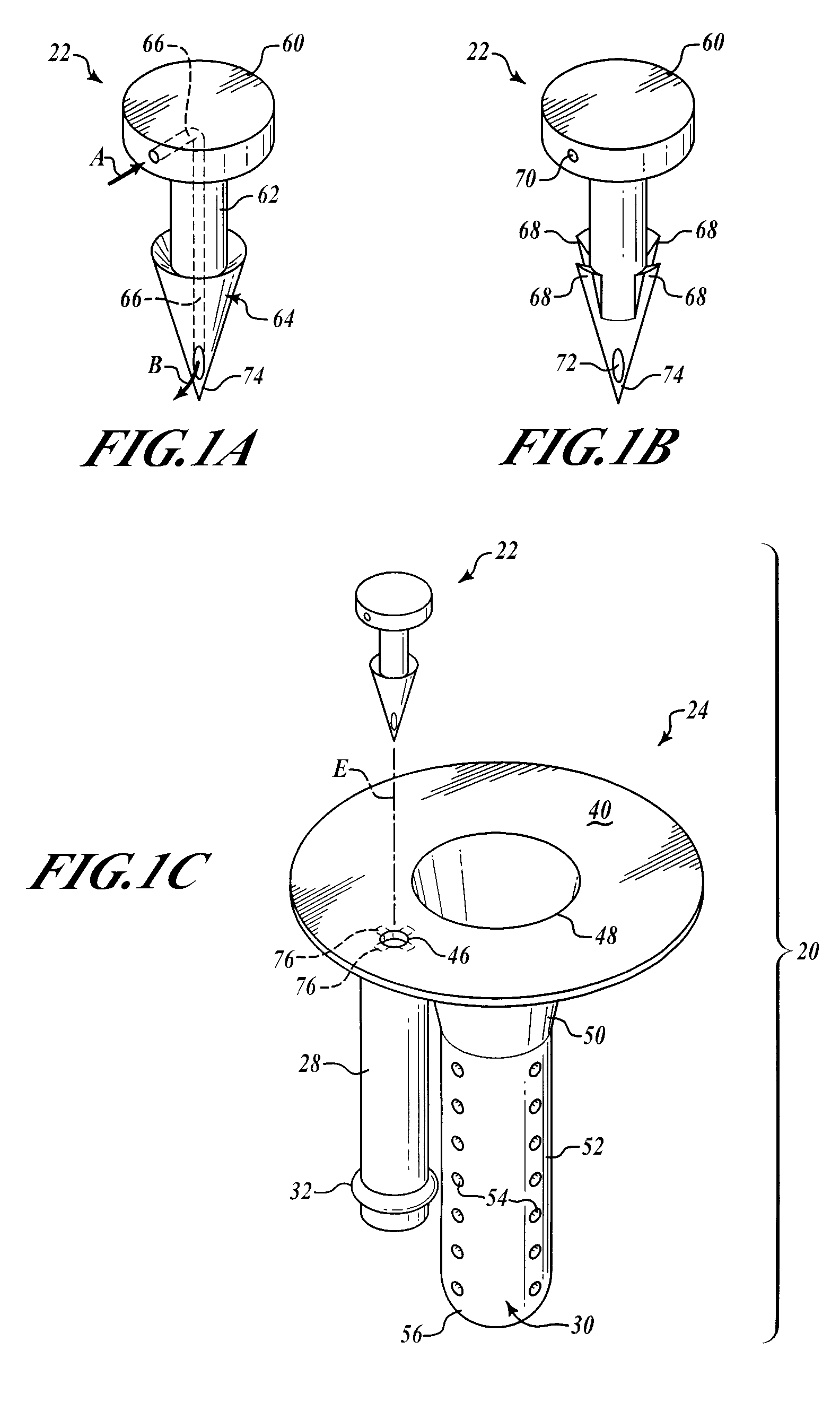
[0042]FIGS. 1A and 1B show two exemplary embodiments of the barbed vent element 22. In FIG. 1A, the barbed vent 22 comprises a flattened stud portion 60 to which is secured a stem portion 62, that terminates in a barb portion 64 that terminates in a sharp piercing point 74. A vent channel or passage 66 is provided internally of the barbed vent 22 extending from an inlet hole 70 in the stud side wall through the stem and terminating in outlet hole 72 adjacent the point 74 (see FIG. 1B). The inlet air is shown by Arrow A and the outlet air by Arrow B in FIG. 1A.

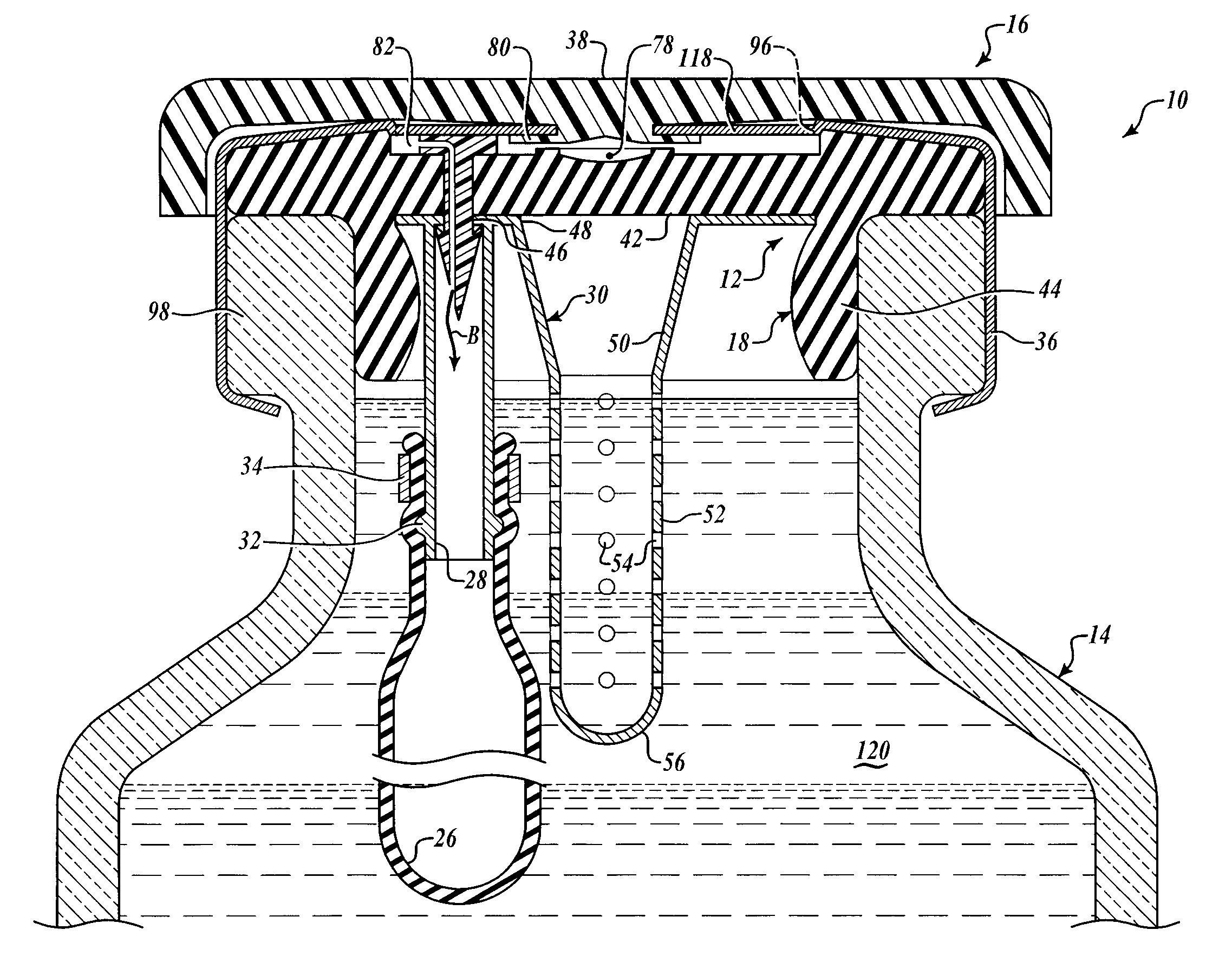
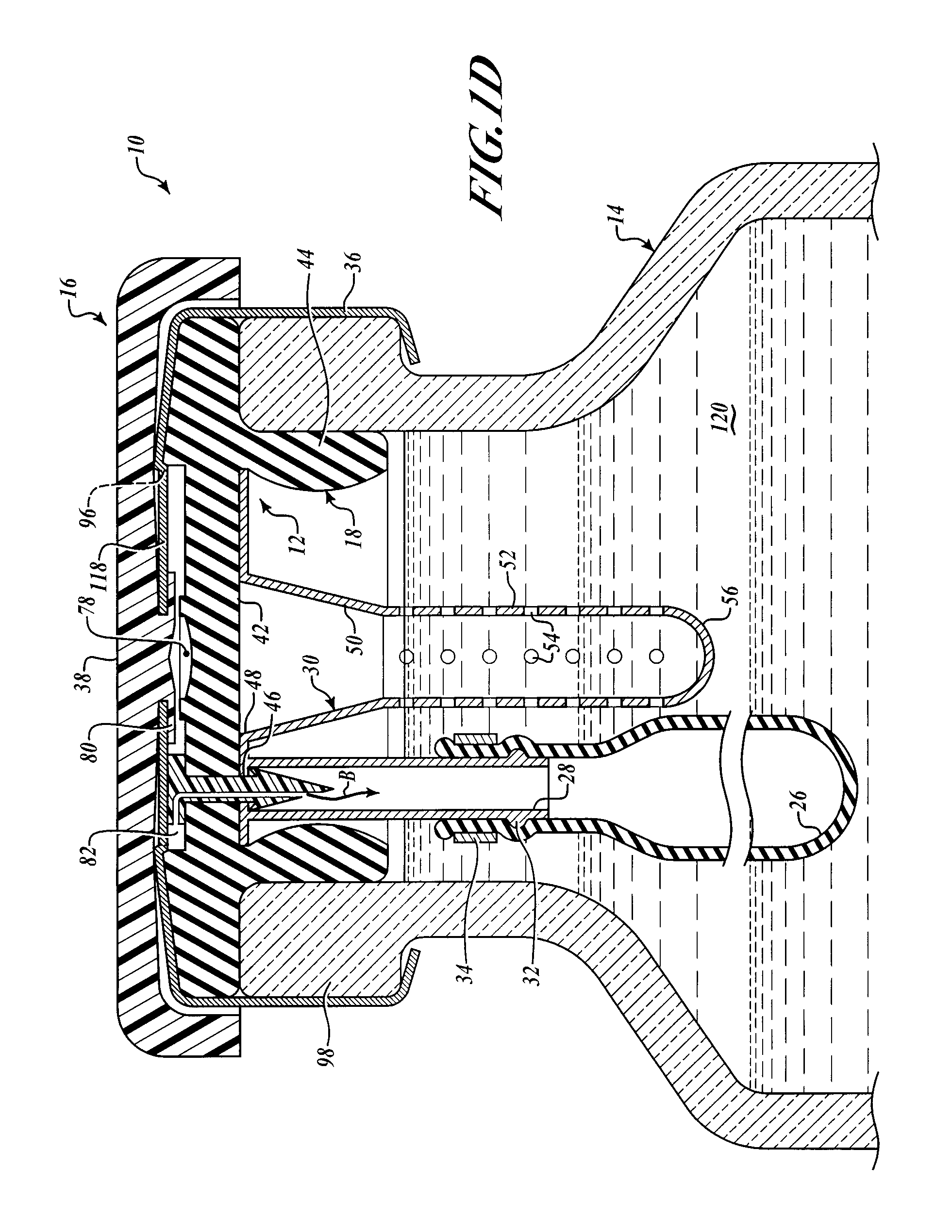
[0043]As seen in FIGS. 1C and 1D, the barbed vent element 22 secures the needle sheath and air bladder retainer assembly 24 to the underside 42 of the stopper collar 44 by application of force to the stud 60 so that the point 74 pierces the stopper neoprene, passes through the hole 46 in the annulus 40 of the needle sheath assembly 30. The barbs engage underside of the annulus adjacent hole 46, as best shown in FIG. 1D, compres...

second embodiment

[0046]FIGS. 2A and 2B show the inventive vacuum-break vial assembly 10, comprising a vial into which is fitted a full length bladder 102 that is made of a medical grade polymer to permit it being filled with a medicinal fluid 120. The bladder is configured with a neck to fit the vial neck, and a lip that generally conforms to the top lip 98 of the vial mouth. The bladder may also be a bellows configuration, or comprise an integral, relatively rigid diaphragm member at the bottom that moves upward as fluid is withdrawn. The vial also includes one or more small air vents 106 so that as fluid is withdrawn from the bladder, air can past into the space between the bladder and inner wall of the vial, permitting the bladder to contract or collapse to compensate for reduction in the volume of fluid in the vial. Recall that the vial is inverted from the orientation shown in this FIG. 2A, so that where the bottom includes a diaphragm member, it will slide down (up in the figure) to compensate...

third embodiment

[0048]FIG. 3 shows the inventive vacuum break vial assembly, in which the needle sheath 100 of FIG. 2A and FIG. 2B is fitted in a stopper with somewhat thickened collar. The cap 14 and flip-off top (not shown) are as in the other embodiments described above. An elongated vent tube 110 is inserted or cast into the wall of the stopper collar 44 as shown, and it terminates at its upper end in an air inlet 114 that provides air vial the holes 54 in the bottom section of the tube. A bladder collar 112 is fitted on the tube 110 and in turn a bladder 26 is secured by the collar. The bladder expansion is shown by Arrows C. The vial volume 116 is filled with medicinal before the stopper having the collapsed bladder wrapped around the air vent tube 110 and needle sheath assembly 100 is inserted into the vial neck. The Arrow D line shows the direction of insertion of the hypodermic in the center of the target ring 78.

[0049]It should be noted that the bladder / bellows / diaphragm may exert either ...


PUM


Abstract

Vacuum break vial assembly and method for reducing the incidence of nosocomial infections, comprising a vial stopper having a 2-part withdrawn-fluid volume compensation assembly having a barbed vent element that secures an apertured needle sheath, a bladder-retainer tube and an expandable/unfoldable bladder. The vial has an aluminum cap holding a plastic flip-off top that removes a central portion of the cap to permit access by hypodermic needle through the stopper into the needle sheath. No pre-pressurization of the vial by ambient contaminated air via the hypodermic can occur. Rather, the needle is inserted in the vial through the stopper and the medicinal fluid withdrawn. Air is inlet into the separate bladder which expands to permit withdrawal of fluid into the hypodermic without vacuum lock. No air having pathogen vectors is introduced into the vial medicinal fluid as the bladder isolates volume-compensating air from the medicinal fluid. Plural embodiments are shown.

Description

CROSS-REFERENCE TO RELATED CASES[0001]This is a CIP of U.S. appplication Ser. No. 11,857,670 filed Sep. 19, 2007 by the same inventor, scheduled to Issue as U.S. Pat. No. 7,618,408B2 on Nov. 17, 2009, which in turn is the Regular US Patent Application corresponding to two Provisional Applications of the same inventor: Ser. No. 60 / 826,287, filed Sep. 20, 2006, entitled Vial Assembly for Reducing Nosocomial Infections, and Ser. No. 60 / 890,134, filed Feb. 15, 2007, entitled Vial Assembly for Reducing Nosocomial Infections—II, the benefit of the filing dates of each of which is claimed under 35 USC 119 and 120, and the disclosures of which are hereby incorporated by reference.FIELD[0002]The invention relates to the field of reducing the incidence of generation and transmission of nosocomial infections, commonly introduced into medicinal injection vials via hypodermic needles followed by transmission upon withdrawal of the infected vial solution and injection into the patients, and more ...

Claims


Application Information

Patent Timeline
IPC IPC(8): A61B19/00
CPCA61J1/1412A61J1/18B65D51/002B65D81/245A61J1/1406A61J2001/1468A61J1/1468
Inventor YANDELL, MARION E.
Owner YANDELL MARION E
Why Eureka
Try Eureka