
Method for magnetron sputter deposition

a magnetron sputter and sputtering technology, applied in the field of magnetron sputter deposition, can solve the problems of inefficiency and/or ineffective efficiency of the line-of-sight process in providing a tubular workpiece coating, and the magnetron sputtering system used to form such a coating generally has been inefficient and/or ineffective, so as to reduce the pressure of the vacuum chamber

Active Publication Date: 2010-09-07
SOUTHWEST RES INST
View PDF60 Cites 12 Cited by
  • Summary
  • Abstract
  • Description
  • Claims
  • Application Information

AI Technical Summary

Problems solved by technology

Although methods exist for depositing protective coatings on planar surfaces, these line-of-sight process are ineffective in providing a coating for a tubular workpiece.
Unfortunately, the magnetron sputtering systems used to form such coatings generally have been inefficient and / or ineffective.

Method used


Image

  • Method for magnetron sputter deposition
  • Method for magnetron sputter deposition
  • Method for magnetron sputter deposition

Examples


Embodiment Construction

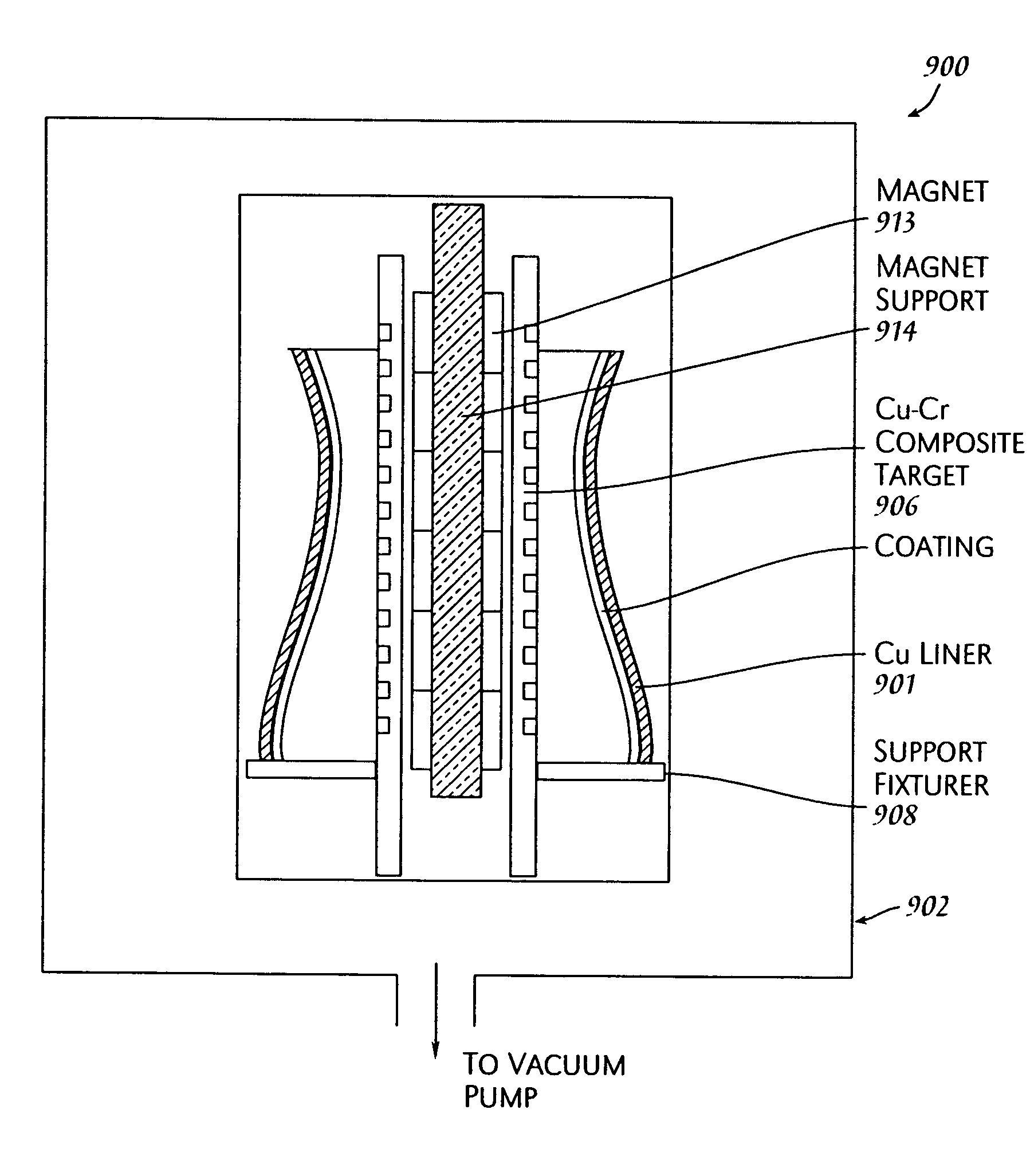
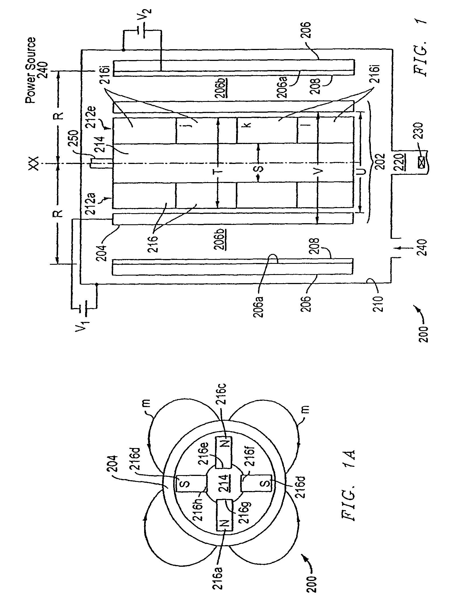
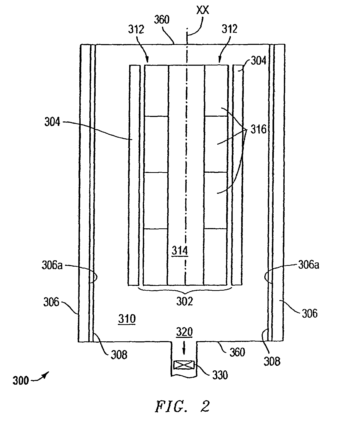
[0047]The present application provides a system, apparatus, and method of depositing a coating on an interior surface of a substrate or workpiece utilizing a magnetron sputtering process. The method of deposition is implemented through operation of a magnetron sputtering system or assembly that includes a magnetron sputtering apparatus (“magnetron”) and the workpiece. The magnetron comprises a sputter target material, from which sputter material is ejected and directed to the workpiece surface to be coated.

[0048]The workpiece is positioned in the vicinity of the magnetron and preferably, such that the interior surface to be coated is facing the sputter target material. The system, apparatus, and method herein are particularly suited for depositing a coating on a hollowed workpiece. Suitable workpieces comprise a hollow or space defined by an interior wall in which the magnetron is positioned. More preferably, the hollowed workpiece comprises a tubular structure having an elongated b...


PUM

PropertyMeasurementUnit
thicknessaaaaaaaaaa
diameteraaaaaaaaaa
discharge voltageaaaaaaaaaa

Abstract

A method for depositing a nanostructured coating comprising chromium or a copper-chromium mixture on a workpiece. The workpiece may comprise a hollowed structure such as a rocket or jet engine combustion chamber liner. The method comprises providing a magnetron and an external sputter target material comprising chromium or a copper-chromium composite and effecting a magnetron sputter deposition to deposit a substantially uniform nanostructured coating comprising said sputter target material on said workpiece. The method may include plasma enhancement wherein a filament is utilized to produce a plasma that effects an ion bombardment on the workpiece during the magnetron sputter deposition process. The invention also includes the nanostructured coatings deposited by these methods and workpieces coated thereby.

Description

CROSS-REFERENCE TO RELATED APPLICATIONS[0001]This application is a continuation-in-part application claiming the benefit of pending U.S. patent application Ser. No. 10 / 963,341, (filed Oct. 12, 2004), entitled “System and Apparatus for Magnetron Sputter Deposition,” and pending U.S. patent application Ser. No. 10 / 962,772, (filed Oct. 12, 2004), entitled “Method for Magnetron Sputter Deposition.” The present application is also related to U.S. patent application Ser. No. 11 / 054,665, (filed Feb. 9, 2005), entitled “Nanostructured Low-Cr Cu—Cr Coatings for High Temperature Oxidation Resistance.” These applications are hereby incorporated by reference in their entireties.FIELD OF THE APPLICATION[0002]The present application relates generally to a method of depositing a nano-structured coating on a workpiece using a magnetron sputter deposition process.BACKGROUND[0003]Tubular workpieces, such as gun barrels and engine cylinders, often require hard, wear-resistant, and / or corrosion resista...

Claims


Application Information

Patent Timeline
Patent Type & Authority Patents(United States)
IPC IPC(8): C23C14/35
CPCC23C14/046C23C14/165C23C14/225C23C14/355H01J37/3405C23C14/352Y10T428/12903
Inventor CHIANG, KUANG-TSAN KENNETHWEI, RONGHUALANGA, EDWARD
Owner SOUTHWEST RES INST
Learn More