Apparatus and method suitable for measuring the global displacement or load on an aircraft component

a technology of aircraft components and apparatus, applied in the direction of instruments, apparatus for force/torque/work measurement, force measurement by measuring optical property variation, etc., can solve the problems of significant horizontal load on landing gear, noise, and associated disadvantages, and achieve the effect of reducing one or more of the disadvantages

Inactive Publication Date: 2010-09-07
AIRBUS OPERATIONS LTD
View PDF33 Cites 7 Cited by
  • Summary
  • Abstract
  • Description
  • Claims
  • Application Information

AI Technical Summary

Benefits of technology

[0005]It is an object of the present invention to provide a load measuring apparatus suitable for external use on an aircraft and which mitigates one or more of the disadvantages outlined above. Alternatively, or additionally, it is an object of the present invention to provide an improved apparatus capable of providing information from which an indication of the load distribution in an aircraft component can be ascertained.

Problems solved by technology

The landing gear is subjected to significant horizontal loads on braking.
These, however, have disadvantages associated with them.
For example, strain gauges may have to be bonded to the structure being monitored, may require specialist maintenance, may only be able to provide a local load measurement, may be easily damaged, may be susceptible to noise and / or may require temperature compensation.
These have disadvantages associated with them, for example they may not be suitable for use on an aircraft in flight and may be costly to fit, and later remove, specifically for a ground vibration test.

Method used


Image

  • Apparatus and method suitable for measuring the global displacement or load on an aircraft component
  • Apparatus and method suitable for measuring the global displacement or load on an aircraft component
  • Apparatus and method suitable for measuring the global displacement or load on an aircraft component

Examples


first embodiment

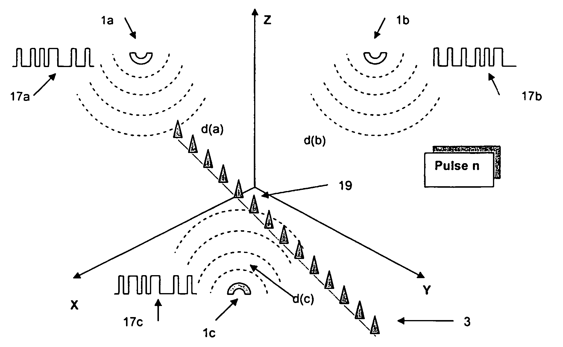
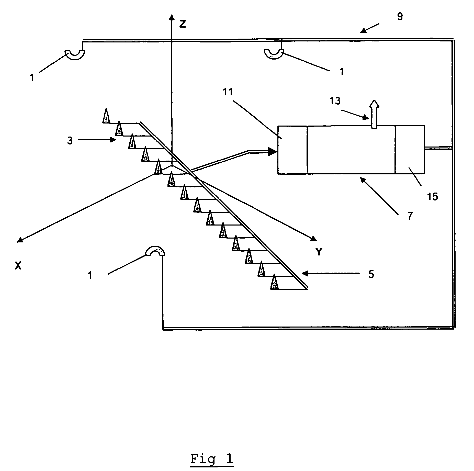
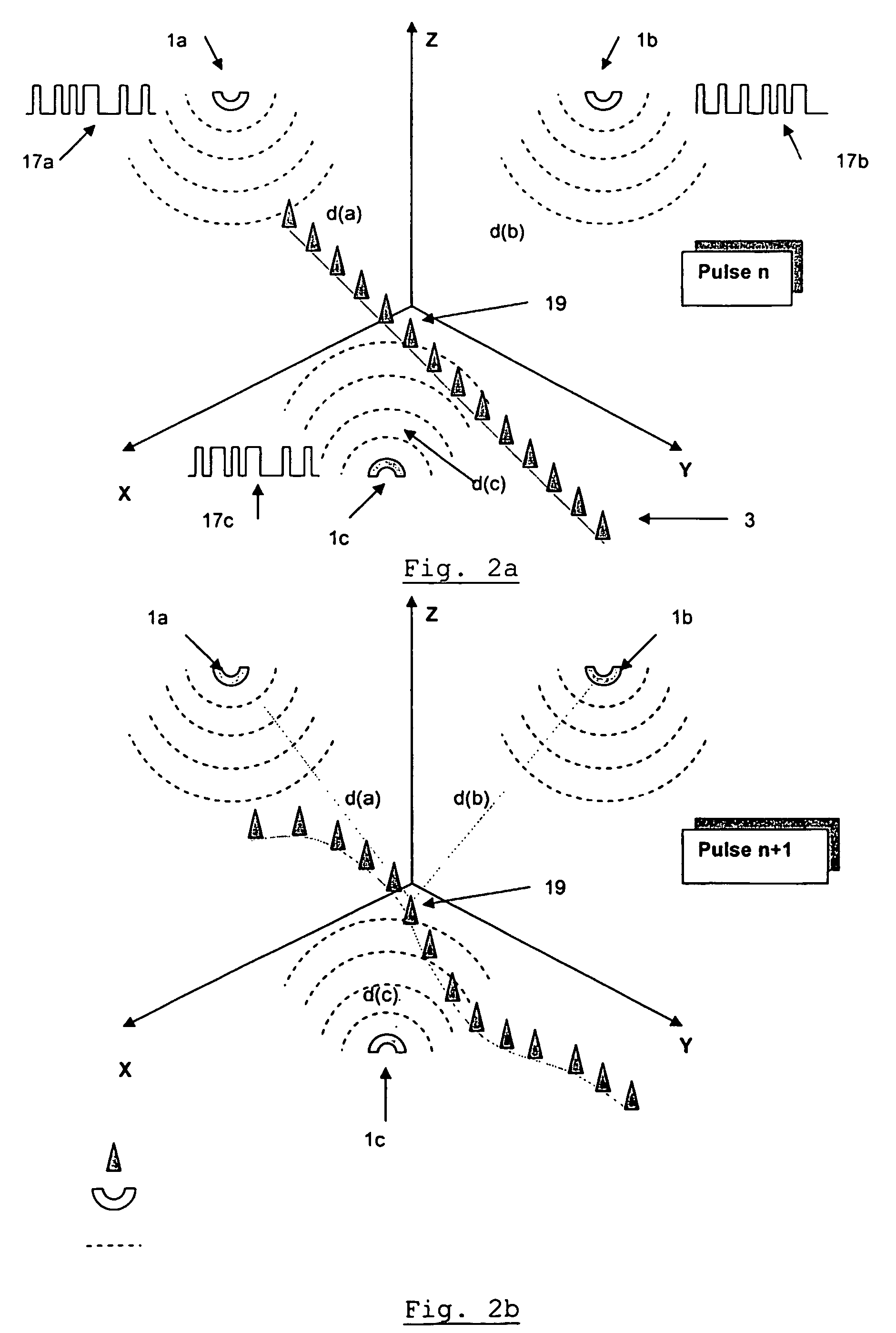
[0060]FIG. 1 shows a schematic of an apparatus for measuring the load on an aircraft according to the invention. The apparatus includes three omni-directional emitters 1 of microwave radiation and fourteen generic microwave detectors 3. Each of the emitters 1 is paired with each of the detectors 3 and, as such, the apparatus effectively includes forty-two pairs of microwave devices. The microwave devices are arranged in various locations in 3-dimensions, which is illustrated schematically by inclusion of the X-Y-Z axes in the figure. The detectors are in the form of microwave antenna receivers. Each antenna receiver is in the form of an omni-directional antenna. Each of the detectors 3 is shielded with material (not shown) that absorbs microwave radiation to reduce the amount of spurious, for example reflected, microwave radiation being received. Apertures, in the form of windows (not shown), are provided which allow the microwave radiation emitted directly from each respective emit...

second embodiment

[0072]In the invention, shown in FIG. 3, the aircraft further includes a load control system. As shown in FIG. 3, the aircraft includes the landing gear assembly 21, comprising the wheel bogie assembly 23, the landing gear leg 25, the brake discs 27 and wheel hubs 29.

[0073]An apparatus for measuring load, for example the apparatus described in the first embodiment, is arranged to measure the load on the landing gear leg 25. Fifteen detectors (not shown) are located at spaced apart positions on the landing gear leg 25, in three parallel and spaced-apart columns positioned on one side of the leg, each column being defined by five detectors. Three emitters are provided on the underside of the aircraft fuselage (not shown). The detectors in this embodiment are in the form of low-profile microstrip antennae and the emitters are omni-directional emitters. The apparatus includes a processing unit (not shown) that functions in the same manner as described above with reference to the first e...

third embodiment

[0077]FIG. 4 shows part of a landing gear assembly on an aircraft according to the invention. Six detectors 3 are located on the outer cylinder 39 of the leg 25 and bogie 23 of the landing gear assembly 42. A single emitter 1 is attached to the airframe of the aircraft and emits a signal received by each detector 3. There are therefore six pairs of devices. The airframe in the region of the emitter 1 displaces relatively little relative to the region of the airframe to which the landing gear assembly attaches. Furthermore, a radio altimeter antenna receiver 43 is attached to the underside of the airframe next to the emitter 1.

[0078]In use, a PTCS 17 is emitted by the emitter 1. After each pulse, the processing unit (not shown) calculates the distance d between the emitter 1 and each detector 3. The radio altimeter antenna receiver 43 is arranged to measure the location of the altimeter relative to ground level. Use of such equipment as an altimeter is well known in the art. The alti...


PUM

PropertyMeasurementUnit
frequencyaaaaaaaaaa
solid angleaaaaaaaaaa

Abstract

The load on an aircraft component is measured. In one embodiment, the system is a contactless, all-weather displacement measuring system including a processing unit and a plurality of pairs of controllable microwave emitters and microwave detectors. When the aircraft component is subjected to a load, relative movement of the emitter and detector is caused. The detector generates signals which convey information concerning the relative positions of the emitter and the detector of the pair, the signals being received and processed by a signal processor of the processing unit. The processing unit may, for example with the use of triangulation techniques, provide an output signal representative of the load sustained by the aircraft component. The system may be used to control braking in dependence on the output signal so as to maximise braking efficiency without overloading the landing gear leg.

Description

BACKGROUND OF THE INVENTION[0001]The present invention relates to an apparatus and a method suitable for measuring the load sustained by an aircraft component. In particular, the present invention relates to an apparatus for determining the load sustained by an aircraft component when braking and / or manoeuvring the aircraft on the ground.[0002]When an aircraft manoeuvres on the ground (including, for example, immediately after touch down), the aircraft is subjected to various loads including vertical wheel to ground loads and horizontal drag loads including, for example, loads caused by friction between the tyres of the wheels of the aircraft and the ground. The landing gear is subjected to significant horizontal loads on braking. The landing gear and other components of the aircraft have to be carefully designed in order for the aircraft to be able to withstand such loads, and other operational loads, but without unduly increasing the mass of the aircraft.[0003]By using a load meas...

Claims


Application Information

Patent Timeline
Patent Type & Authority Patents(United States)
IPC IPC(8): G01L1/24B60T8/32B60T8/52B64C25/00B64C25/44B64C25/46B64C25/58G01L1/25
CPCB60T8/325B60T8/52B64C25/001B64C25/445B64C25/46B64C25/58G01L1/25
Inventor GIAZOTTO, ALESSANDRO RICCARDO BRITANNICO
Owner AIRBUS OPERATIONS LTD
Why Eureka
Try Eureka