Optical alignment system and alignment method for radiographic X-ray imaging

a radiographic x-ray and optical alignment technology, applied in the field of imaging systems, can solve the problems of insufficient adjustment, difficult or impossible to use the visible beam to align the x-ray mirror, and single mirror will only yield a thin fan-beam of mono-energetic x-ray light, etc., to eliminate discrepancies and eliminate discrepancies

Inactive Publication Date: 2010-09-14
REFLECTIVE X RAY OPTICS
View PDF16 Cites 23 Cited by
  • Summary
  • Abstract
  • Description
  • Claims
  • Application Information

AI Technical Summary

Benefits of technology

[0012]In one embodiment, the invention is an X-ray optical alignment system for X-ray imaging devices utilizing a point-source X-ray tube having an X-ray focal spot (and optionally utilizing X-ray mirrors for beam filtration). A visible-light point source is provided, as is a multi-axis positioner, coupled to the light source and fixedly mounted with respect to the X-ray focal spot. The multi-axis positioner enables spatial and angular adjustment of the visible-light point source. A mirror is fixedly mounted with respect to the X-ray focal spot and disposed in the beam path of the X-ray source, reflecting light emitted from the visible-light point source and transmitting X-rays emitted from the X-ray source. Preferably, the mirror is a beamsplitter, more preferably a pellicle beamsplitter. A first X-ray attenuating grid is fixedly but removably mountable with respect to the X-ray source and has a first X-ray attenuation pattern. A second X-ray attenuating grid is adjustably mountable with respect to the first grid and has a second X-ray attenuating pattern corresponding to the first X-ray attenuating pattern. When the first and second grids are aligned, the first and second attenuating patterns are also aligned and thereby allow X-rays from the X-ray source and light reflected from the mirror to pass therethrough.
[0017]The invention also includes a method for aligning a visible light alignment system and an X-ray imaging system of an X-ray imaging device, where the X-ray imaging system utilizes a point-source X-ray tube having an X-ray focal spot and optionally X-ray mirrors for beam filtration, and the visible light alignment system has a visible light point source. First, two X-ray attenuating alignment grids are fixedly attached a first distance apart from each other and a second distance apart from the X-ray focal spot, each grid having an attenuation pattern formed respectively therethrough to selectively block both X-rays and visible light. Next, a pattern of the X-rays from the X-ray source that pass through both alignment grids is detected. The relative misalignment of the two alignment grids based on the resultant detected X-ray pattern is determined and compared to the attenuation patterns of the two grids. The position of one of the grids is adjusted relative to the other grid so as to eliminate discrepancies between the detected X-ray pattern and the attenuation patterns of the grids. When the recorded X-ray pattern is substantially identical to the attenuation grid patterns after iterating these last two steps, the visible light source is activated, and relative misalignment of the two alignment grids and the visible light source are determined based on the resultant visible light pattern transmitted through the two grids. Finally, the position of the visible light source is adjusted so as to eliminate discrepancies between the transmitted visible light pattern and the attenuation patterns of the grid.

Problems solved by technology

Because the mirrors only work at shallow grazing incidence angles, a single mirror will only yield a thin fan-beam of mono-energetic X-ray light.
The same visible light alignment system could also be used to align the mirrors themselves, in principle, which is an otherwise difficult task, again provided that the visible / X-ray misalignment is sufficiently small.
While the misalignments permitted under governmental regulations are adequate for patient registration, such misalignments are completely inadequate for use with the X-ray mirrors designed to produce mono-energetic radiation that operate a relatively shallow grazing incidence angles: i.e., when X-ray mirrors are placed in the X-ray beam, the typical misalignments between the visible and X-ray beams in a conventional alignment system will make it difficult or impossible to use the visible beam to align the X-ray mirrors.
Additionally, conventional visible-light alignment systems do not provide sufficiently precise adjustments of the position of the visible light source relative to the virtual focal point, and furthermore, the size of the light-emitting region itself is large relative to the X-ray focal spot size.
Thus, conventional visible light systems are generally inadequate for use when X-ray mirrors are implemented.

Method used


Image

  • Optical alignment system and alignment method for radiographic X-ray imaging
  • Optical alignment system and alignment method for radiographic X-ray imaging
  • Optical alignment system and alignment method for radiographic X-ray imaging

Examples


Embodiment Construction

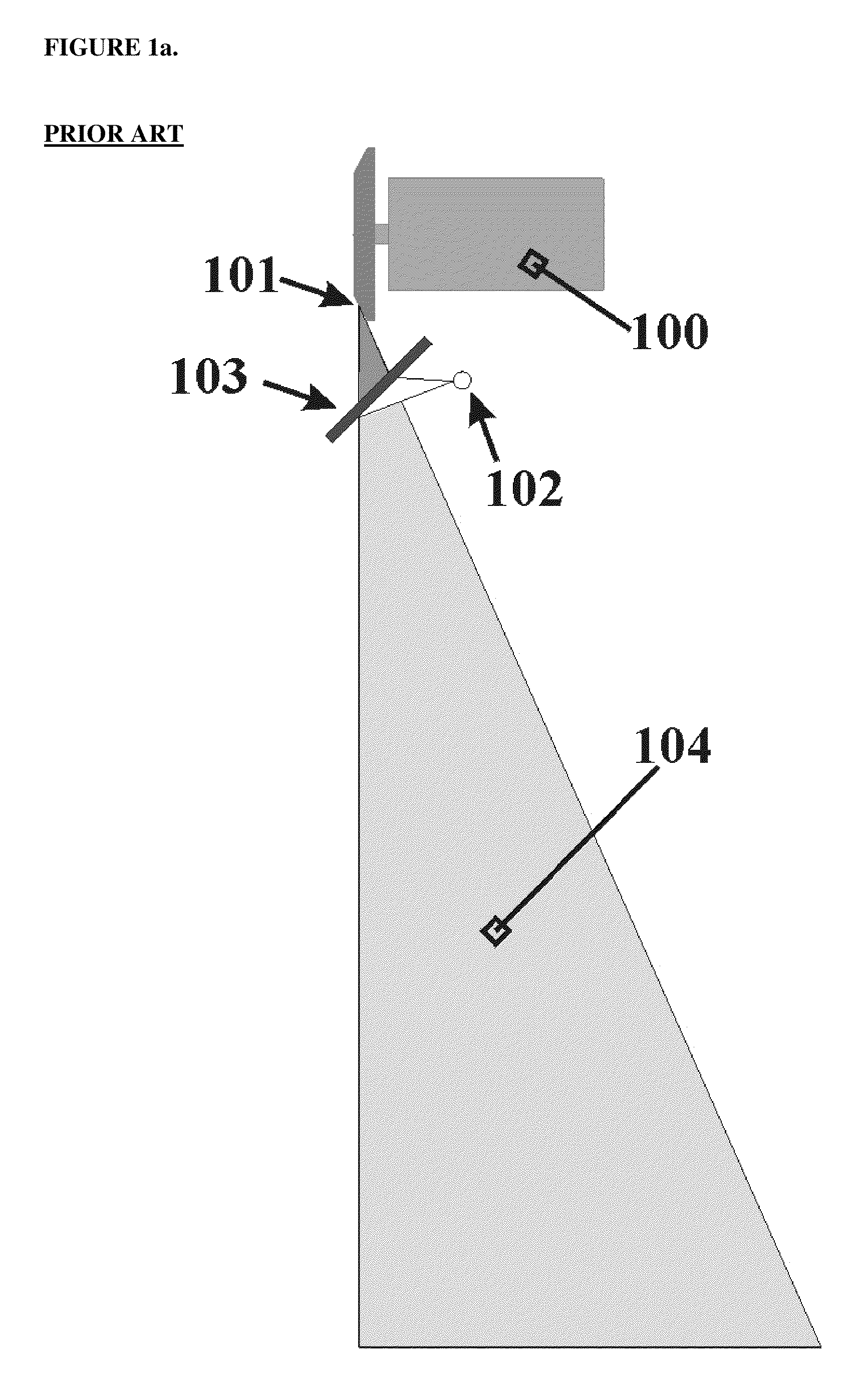
[0025]A conventional visible-light alignment system (FIG. 1a) commonly used in radiographic X-ray imaging systems includes an incandescent light bulb (102) and a 45-degree mirror (103) mounted in a fixed position relative to a point-source X-ray tube (100). The light bulb (102) is positioned at a virtual focal spot defined by the actual X-ray focal spot (101) and the angle and location of the 45-degree mirror relative to the X-ray spot. The visible-light cone beam overlaps with the X-ray cone beam (104), thereby providing a method for visual observation of the X-ray field at the object and / or image plane.

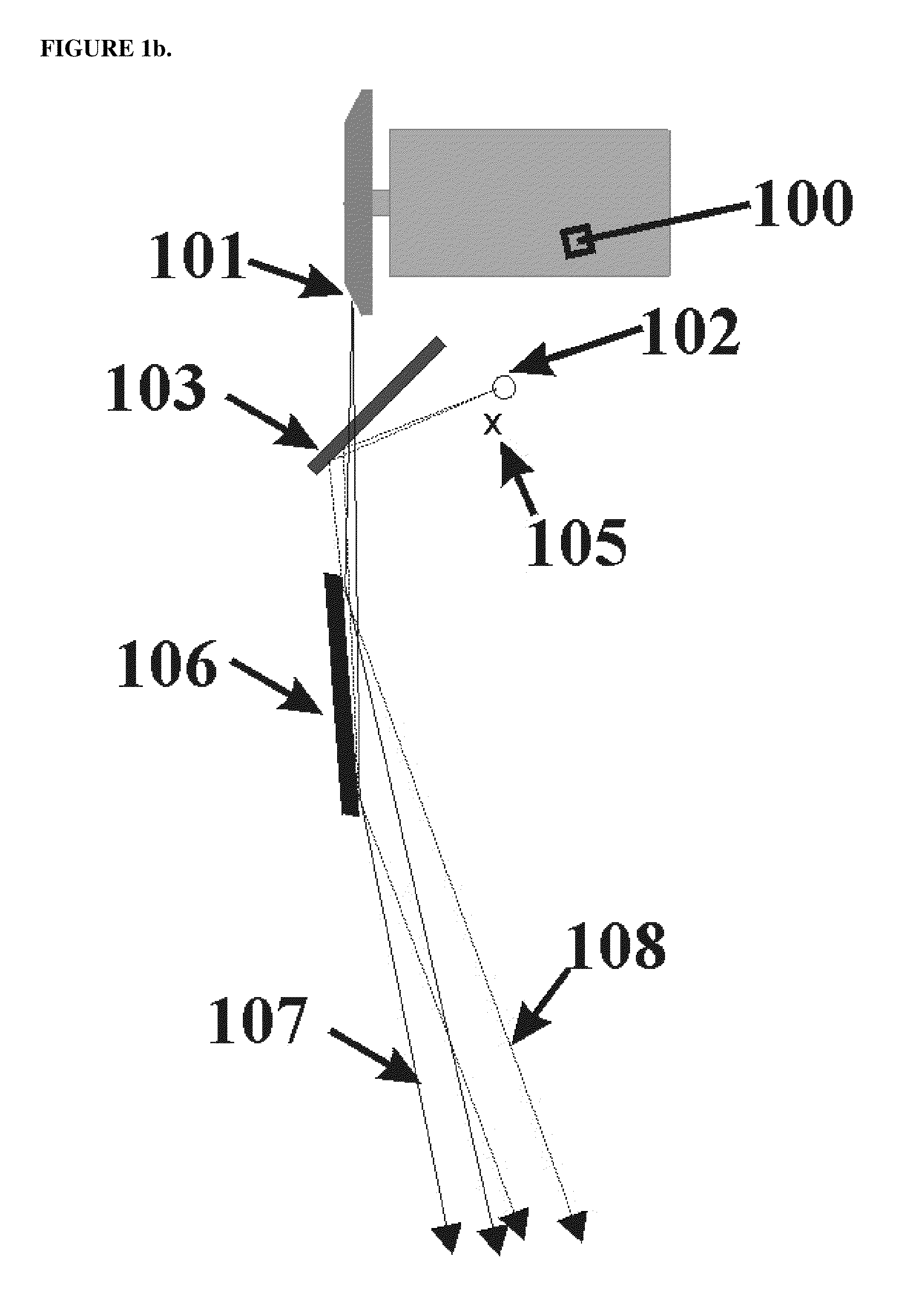
[0026]A radiographic X-ray imaging system incorporating a single multilayer X-ray mirror for beam filtration is shown in FIG. 1b. The X-ray mirror (106) must be precisely positioned in the X-ray beam. A virtual focal spot (105) is determined by the position and angle of the 45-degree mirror (103) relative to the X-ray spot. When the light source (102) used in the visible alignment s...


PUM


Abstract

An X-ray optical alignment system for X-ray imaging devices includes a visible-light point source and a multi-axis positioner therefor, fixedly mounted with respect to the X-ray focal spot. A mirror or beamsplitter is fixedly mounted with respect to the X-ray focal spot and disposed in the beam path of the X-ray source. The beamsplitter reflects light emitted from the light source and transmits X-rays emitted from the X-ray source. A first X-ray attenuating grid is fixedly but removably mountable with respect to the X-ray source, having a first X-ray attenuation pattern; and a second X-ray attenuating grid is adjustably mountable with respect to the first grid having a second X-ray attenuating pattern corresponding to the first X-ray attenuating pattern. When the grids are aligned, their attenuating patterns are also aligned and allow X-rays from the X-ray source and light reflected from the beamsplitter to pass therethrough.

Description

RELATED APPLICATIONS[0001]Domestic priority is claimed from U.S. Provisional Patent Application No. 61 / 062,459 entitled “Optical Alignment System and Alignment Method for Radiographic X-Ray Imaging” filed Jan. 28, 2008, the entirety of which is incorporated by reference herein.BACKGROUND OF THE INVENTION[0002]1. Field of the Invention[0003]The invention is directed to imaging systems, and more particularly to radiographic X-ray imaging systems, for medical, industrial, and other applications.[0004]2. Description of Related Art[0005]Radiographic X-ray imaging systems for medical, industrial and other applications typically use a point-source X-ray tube in which energetic electrons impinge upon a solid metal target thereby producing a cone-beam of X-ray light emanating from the focal spot. The spectrum of X-rays emitted from such tubes is poly-energetic, having line emission characteristic of the anode material used in the tube (commonly tungsten, or in the case of mammography, molybd...

Claims


Application Information

Patent Timeline
Patent Type & Authority Patents(United States)
IPC IPC(8): A61B6/08G01D18/00
CPCA61B6/08A61B6/583A61B6/06A61B6/4035A61B6/4078A61B6/4085A61B6/502A61B6/582A61B6/587
Inventor WINDT, DAVID L.
Owner REFLECTIVE X RAY OPTICS
Why Eureka
Try Eureka