
X-ray apparatus

a technology of x-ray tubes and x-ray tubes, which is applied in the field of x-ray tubes, can solve the problems of imposing difficulties, limiting the choice and specification of x-ray tubes that can be used, and placing limitations on the apparatus design, so as to optimise the performance of the x-ray tube, the choice of tube designs and capacities can be widened

Active Publication Date: 2010-09-14
ELEKTA AB
View PDF9 Cites 145 Cited by
  • Summary
  • Abstract
  • Description
  • Claims
  • Application Information

AI Technical Summary

Benefits of technology

The present invention provides an X-ray apparatus that can be rotated to direct the X-ray beam towards the rotation axis, allowing for improved image quality and flexibility in the choice of X-ray tubes. The X-ray source is offset from the rotation axis by a few degrees, which allows the entire field of the X-ray tube to be utilized. This also helps to keep away from potential image distortion caused by edge effects in the X-ray tube.

Problems solved by technology

Whilst this arrangement is potentially beneficial in that it allows a different compromise to be reached between aperture and image quality in cases that demand it, it does place some limitations on the apparatus design.
This limits the choice and specification of X-ray tubes that can be used and may impose difficulties in other areas, in that a tube that is able to provide a sufficiently wide beam may be inadequate in other ways.

Method used


Image

  • X-ray apparatus
  • X-ray apparatus
  • X-ray apparatus

Examples


Embodiment Construction

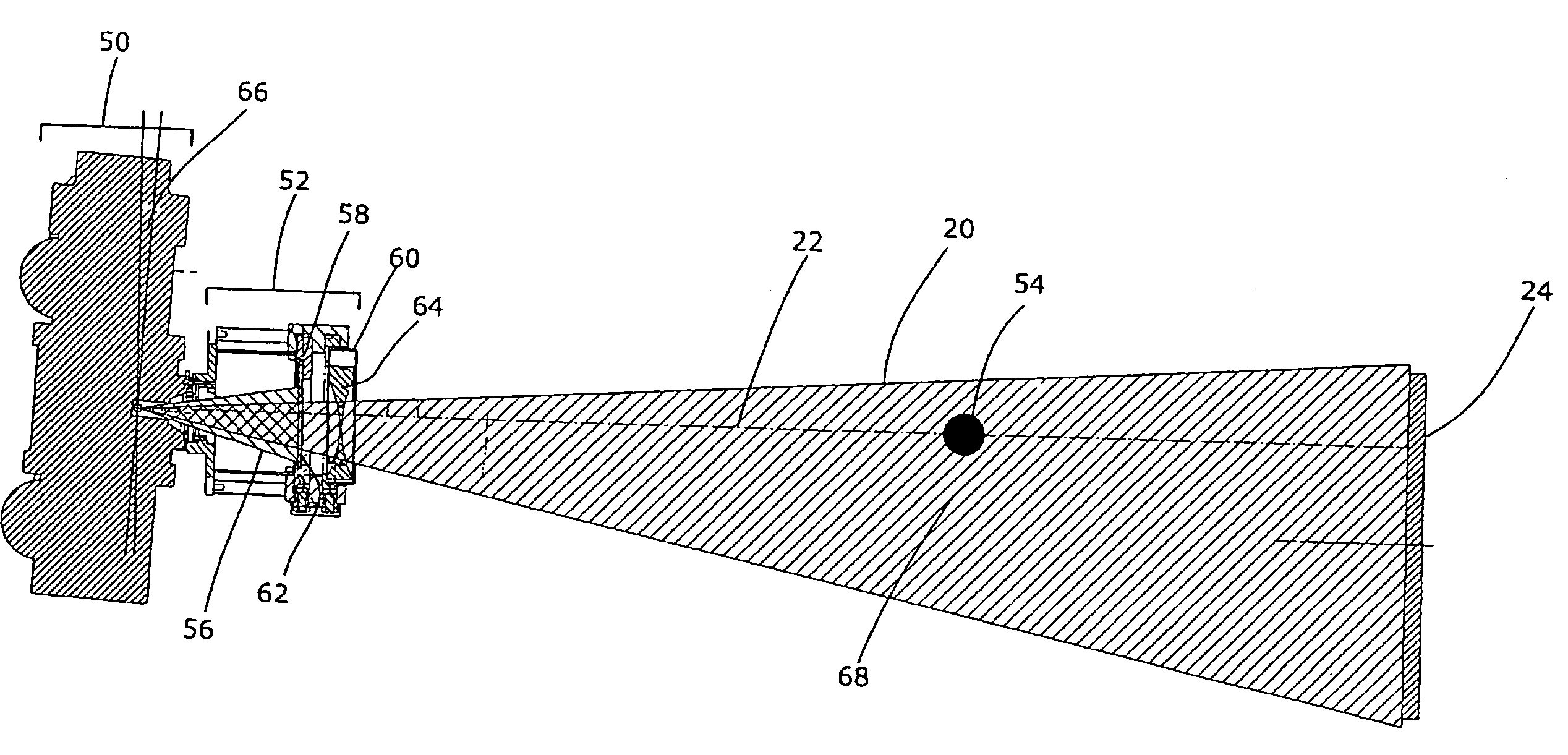
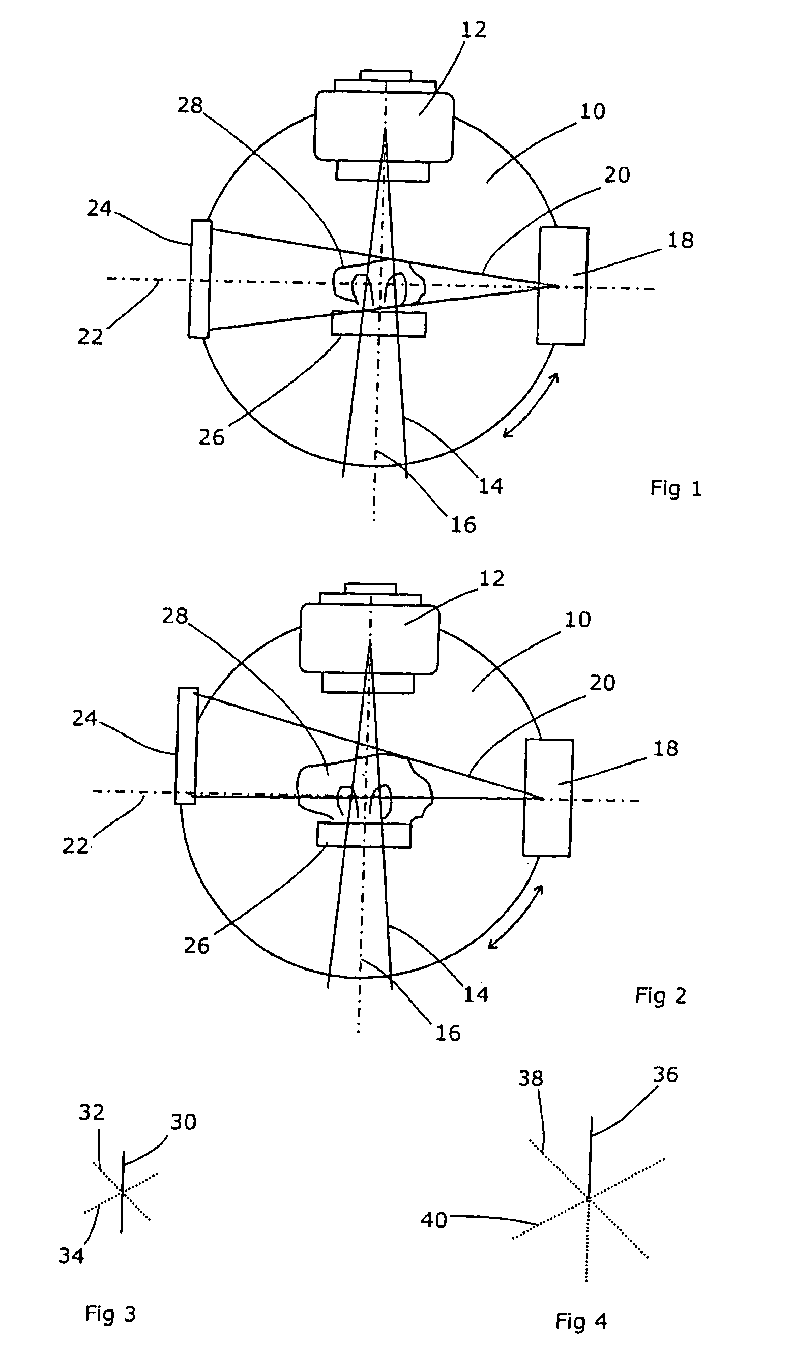
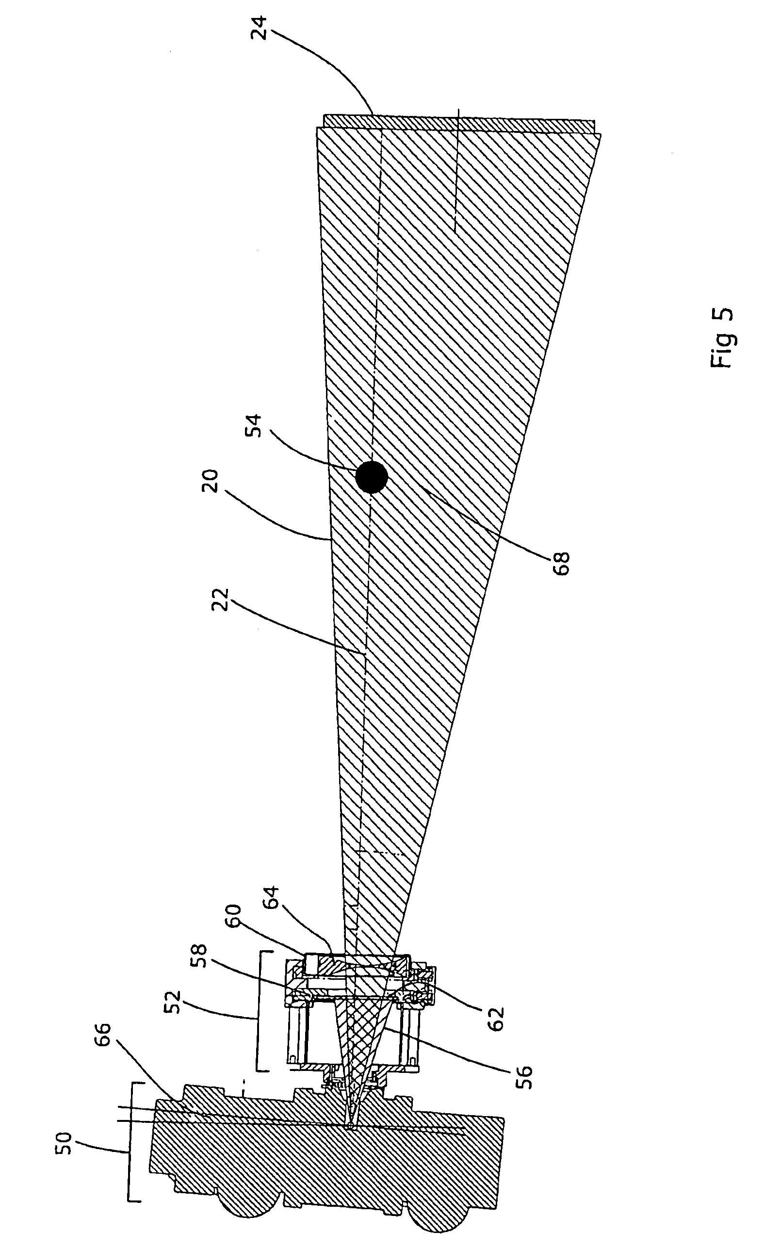
[0020]FIG. 1 shows a typical radiotherapy machine. This has a rotatable support 10 on which is mounted a therapeutic X-ray source 12 which is able to produce a collimated beam of high energy X-rays 14 centred on a therapeutic beam axis 16. Also mounted on the rotatable support 10 is an investigative X-ray source 18, which produces a beam of low-energy X-rays 20 along an investigative beam axis 22. On the opposite side of the support 10, a flat panel detector 24 is positioned so as to intersect with the investigative beam axis 22.

[0021]The rotatable support 10 is arranged to rotate about an axis which passes through the coincidence of the therapeutic beam axis 16 and the investigative beam axis 22, and which is orthogonal to both axes. In this case, the therapeutic beam axis and the investigative beam axis are orthogonal to each other, but this is not essential and other designs are possible. The point of coincidence of the two beam axis 16, 22 and the rotation axis of the support 10...


PUM

PropertyMeasurementUnit
voltageaaaaaaaaaa
energyaaaaaaaaaa
Computed Tomographyaaaaaaaaaa

Abstract

An investigative X-ray apparatus comprises a source of X-rays emitting a cone beam centred on a beam axis, a collimator to limit the extent of the beam, and a two-dimensional detector, the apparatus being mounted on a support which is rotatable about a rotation axis, the collimator having a first state in which the collimated beam is directed towards the rotation axis and the second state in which the collimated beam is offset from the rotation axis, the two-dimensional detector being movable accordingly, the beam axis being offset from the rotation axis by a lesser amount than the collimated beam in the second state. The X-ray source is no longer directed towards the isocentre as would normally be the case; the X-ray source is not orthogonal to the collimators. This is advantageous in that the entire field of the X-ray tube can be utilised. As a result, a lesser field is required of the X-ray tube and the choice of tube designs and capacities can be widened so as to optimise the performance of the X-ray tube in other aspects.

Description

CROSS-REFERENCE TO RELATED APPLICATION[0001]This application is a Section 371 National Stage Application of International Application No. PCT / GB2005 / 002894, filed 25 Jul. 2005 and published as WO 2006 / 013325 on 9 Feb. 2006, in English.FIELD OF THE INVENTION[0002]The present invention relates to X-ray apparatus, in particular X-ray apparatus that has an investigative function. Such X-ray apparatus can be stand-alone X-ray apparatus, for purely investigative purposes, or can be integrated as part of an investigative function provided on a radiotherapeutic apparatus.BACKGROUND ART[0003]Computed Tomography scanning is a well known diagnostic technique and, in Its cone beam form, involves directing a wide beam of X-rays towards and through the patient and capturing the resulting two-dimensional image on a flat panel detector behind the patient. The apparatus (source and detector) is then rotated around the patient to obtain a multiplicity of images from different directions. These images...

Claims


Application Information

Patent Timeline
Patent Type & Authority Patents(United States)
IPC IPC(8): A61N5/10G21K1/04A61B6/03A61B6/06G01N23/04G21K1/02G21K1/10
CPCA61B6/032A61B6/4035A61B6/5241A61B6/587G21K1/02G21K1/10A61N2005/1061A61B6/4021
Inventor BERGFJORD, PER HARALD
Owner ELEKTA AB
Learn More