Gyroscope with temperature compensation

a gyroscope and temperature compensation technology, applied in the direction of instruments, heat measurement, navigation instruments, etc., can solve the problems of non-linear temperature dependence of bias and scale factors inability to account for changes in scale factors, and unique challenges in the use of piezoelectric gyro resonators to infer temperature from the operating, so as to improve reliability and durability of gyro reson

Inactive Publication Date: 2010-09-21
WATSON INDUSRIES
View PDF16 Cites 24 Cited by
  • Summary
  • Abstract
  • Description
  • Claims
  • Application Information

AI Technical Summary

Benefits of technology

[0012]Various embodiments of the invention are presented that include a monolithic vibrating structure such as a piezoelectric resonator and that utilizes the temperature dependency of the resonant frequency of the resonator to determine the temperature of the resonator. The use of monolithic vibrating structures can improve reliability and durability of the gyro resonator because they are not composite structures. Some embodiments of the invention utilize changes in attendant operating characteristics of the gyro resonator other than resonant frequency, such as drive signal, to correlate with and compensate for the temperature drift of the gyroscope. Certain embodiments further utilize alternative configurations other than the ring gyro resonator, such as a cup (cylindrical or hemispherical) or fork geometry that are less prone to lead or lag between the resonator and the drive and / or sense components in response to external temperature changes. Accordingly, the various embodiments of the invention can eliminate or reduce the vagrancies associated with silicon ring gyro resonators.

Problems solved by technology

Furthermore, it has been discovered that the power series expansion technique of Malvern, as described above, does not account for changes in the scale factor due to the thermal lead or lag.
The use of piezoelectric gyro resonators pose unique challenges to inferring temperature from the operating characteristics.
Furthermore, while the variation in both the bias and the scale factor with temperature are generally linear for silicon ring gyro resonators, the temperature dependency of the bias and scale factors of piezoelectric gyro resonators can be substantially non-linear.

Method used


Image

  • Gyroscope with temperature compensation
  • Gyroscope with temperature compensation
  • Gyroscope with temperature compensation

Examples


Embodiment Construction

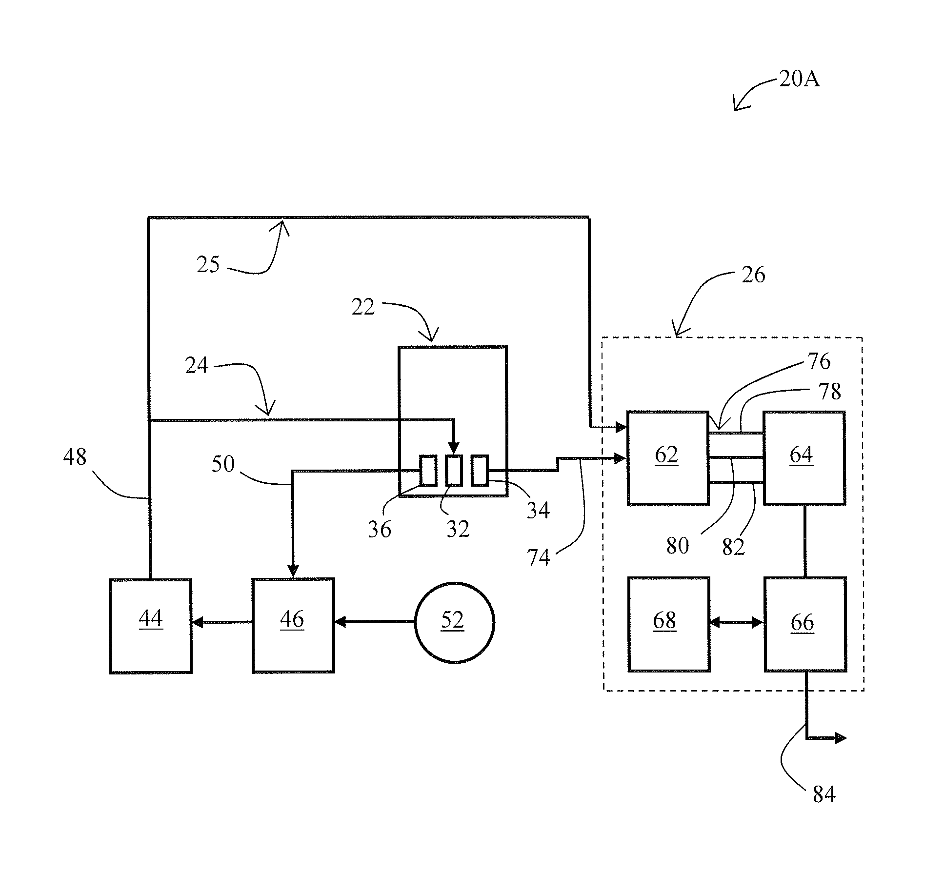
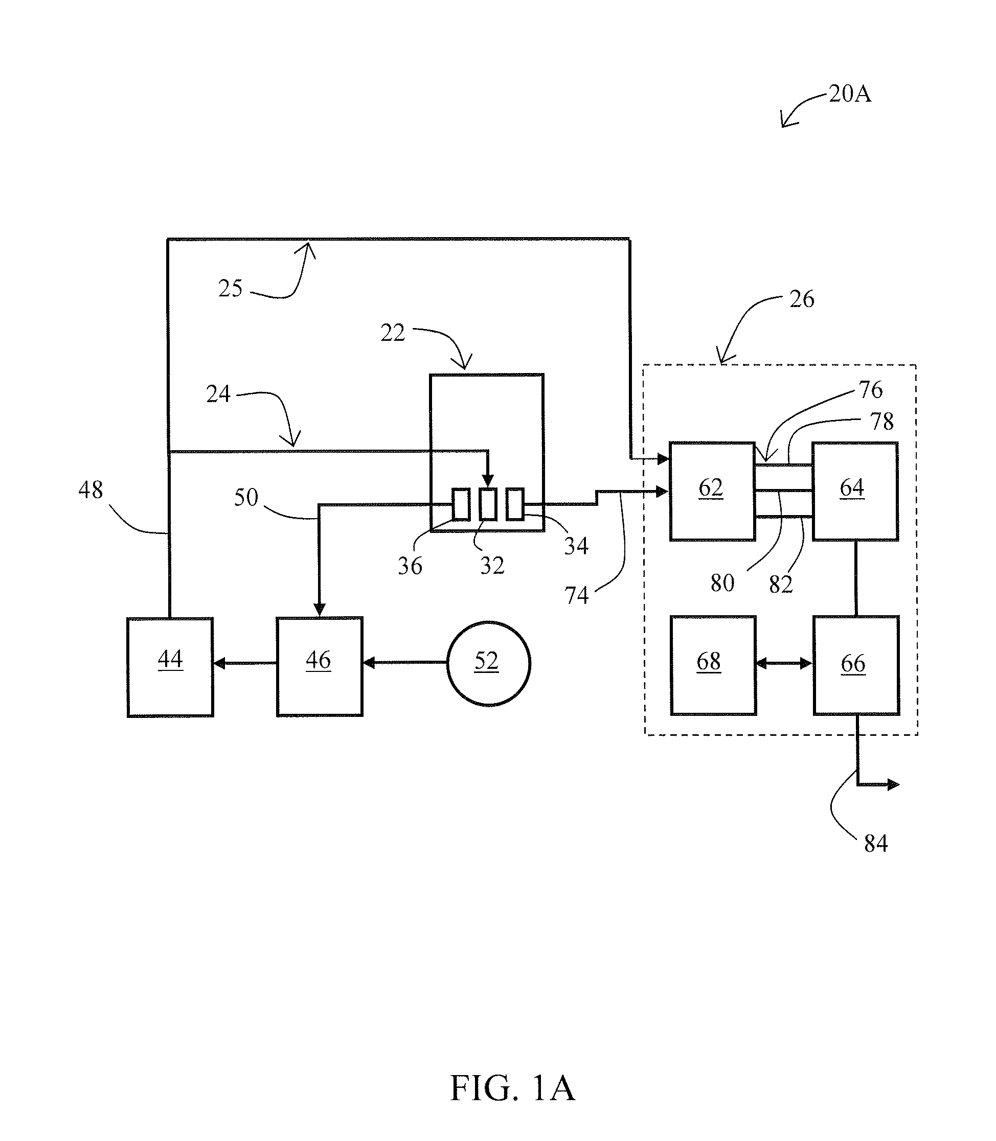
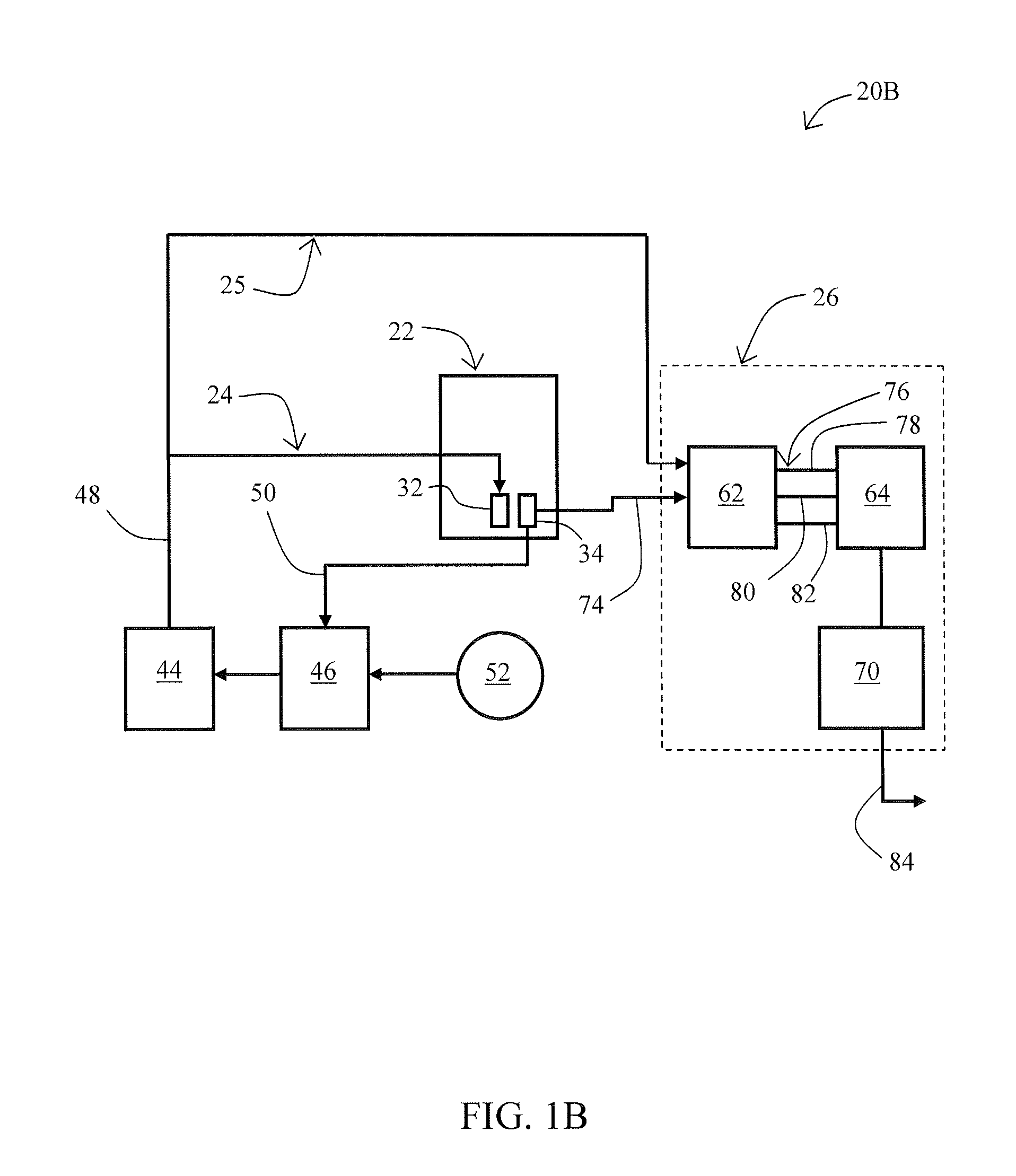
[0028]Referring to FIGS. 1A and 1B, a gyroscope system 20A or 20B is depicted in an embodiment of the invention. The gyroscope system 20A may include a piezoelectric gyro resonator 22, a drive control loop 24, a phase reference connection 25 for demodulating the rotation rate signal, and an output processor 26. The piezoelectric gyro resonator 22 may include at least one drive element 32 for generating a vibration pattern on the piezoelectric gyro resonator 22 and at least one sensing element 34 positioned on the piezoelectric gyro resonator 22 at a location of the node of the vibration pattern for detecting a minimum or near-minimum signal when the piezoelectric gyro resonator 22 is being driven (vibrated) but is rotationally at rest.

[0029]The gyroscope system 20A may further include a dedicated feedback element 36 (as depicted) that is substantially distanced from any node locations of the at-rest vibration pattern for detection of the amplitude of the oscillation pattern. The dri...


PUM


Abstract

A method for compensating for bias and scale factor errors in vibrating structure gyroscopes. Certain embodiments utilize the functional relationship that bias and scale factor errors have with resonant frequency of vibration in the main vibrating body. Other embodiments utilize the functional relationships that other drive parameters of vibrating structure gyroscopes, such as drive voltage, have with bias and scale factor errors. The various methods may be used repeatedly during normal gyroscope operation in order to continually compensate for the bias and scale factor errors.

Description

RELATED APPLICATIONS[0001]The present application claims the benefit of U.S. Provisional Application No. 60 / 975,629, filed Sep. 27, 2007, which is incorporated by reference herein in its entirety.FIELD OF THE INVENTION[0002]The present disclosure relates generally to instruments and methods for determination of rate of rotation. More specifically this disclosure relates to methods for temperature compensation in angular-rate gyroscopes.BACKGROUND OF INVENTION[0003]Gyroscopes have found application in the sensing of angular rotation rate. The design and packaging of gyroscopes has evolved as new applications for their rate-sensing capabilities have been realized. For instance, gyroscopes have been utilized in airplane navigation systems, weapon navigation systems, and boat stabilization systems. More recently, gyroscopes have been utilized in applications such as stabilizing a camera lens and in providing real time feedback for interactive game consoles indicating when a control devi...

Claims


Application Information

Patent Timeline
Patent Type & Authority Patents(United States)
IPC IPC(8): G01C19/00G06F19/00
CPCG01C19/56G01C25/005G01C21/183
Inventor WATSON, WILLIAM S.
Owner WATSON INDUSRIES
Why Eureka
Try Eureka