
Plastic ball grid array ruggedization

a grid array and plastic ball technology, applied in the direction of soldering apparatus, semiconductor/solid-state device details, manufacturing tools, etc., can solve the problems of premature failure in dod field environments, affecting the alignment of columns, and high levels of solder joint strain, so as to reduce warping, increase the reliability of the solder joint, and the effect of flatness over temperatur

Active Publication Date: 2010-09-28
LOCKHEED MARTIN CORP
View PDF13 Cites 0 Cited by
  • Summary
  • Abstract
  • Description
  • Claims
  • Application Information

AI Technical Summary

Benefits of technology

[0014]The solder joint reliability of PBGA components may be increased by replacing its solder balls with high melt solder columns. In addition, prior to adding the columns, a stiffener is bonded to the top of the component to maintain flatness over the temperature ranges associated with both the solder column attach and assembly soldering processes. The invention replaces solder balls with columns, which may be high melt solder, copper wire, or others, to increase strain relief between component and printed wiring board.
[0017]The stiffener is a thin metal or ceramic plate (or it can be a frame type or other type having a planar surface with a lip around the edge that mates with the columns) which is bonded to the top of the PBGA to maintain its flatness over temperature during the column attach process. It has been found using moire interferrometry that bonding an aluminum plate to the top of a PBGA can result in a significant reduction in warping during temperature cycling. This allows attachment of solder columns to the PBGA without a misalignment of the columns. This combination of a stiffener and high melt solder columns increases the solder joint reliability of the PBGA.
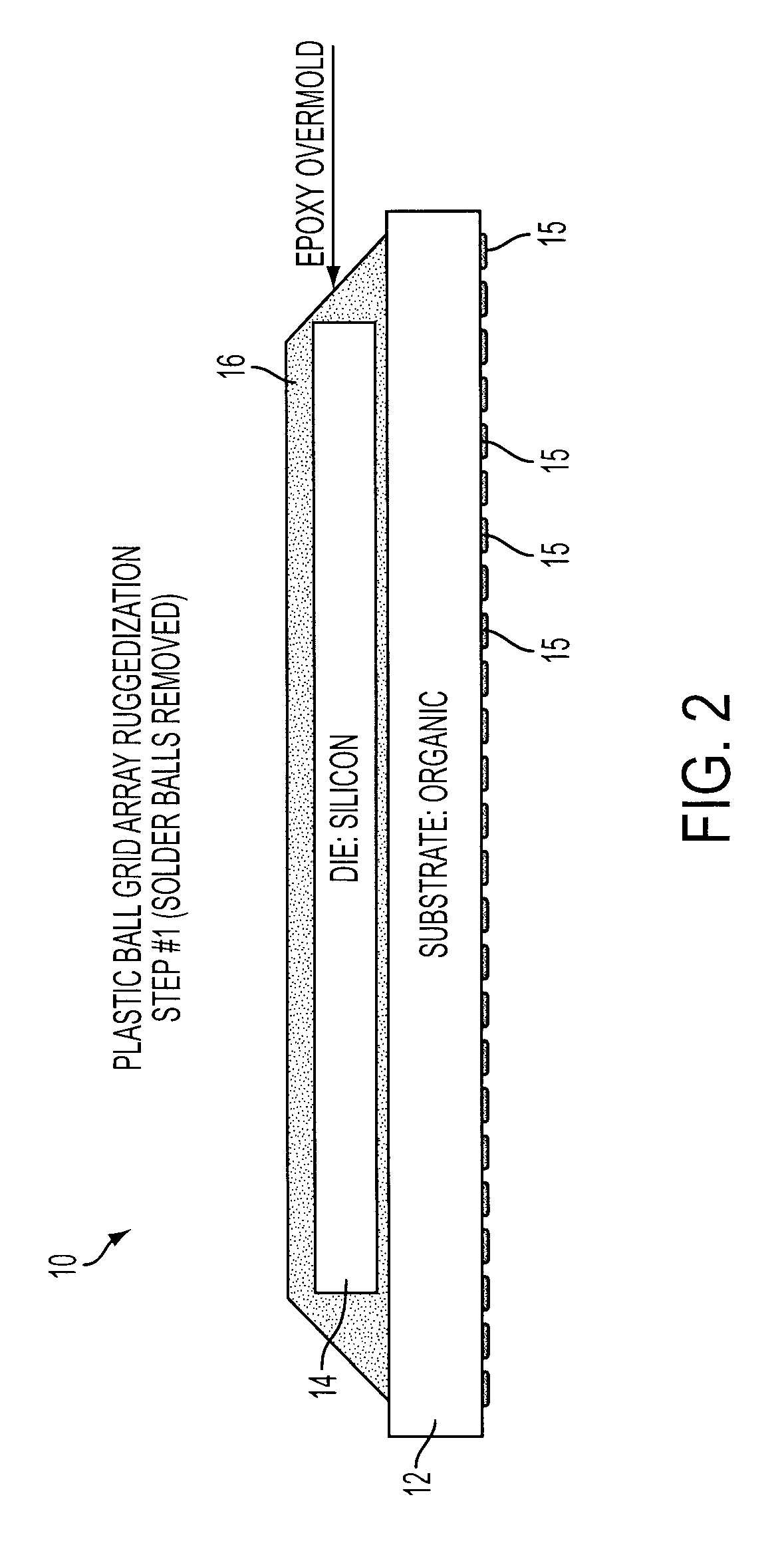
[0018]In the retrofitting process, the solder balls are replaced with columns (high melt solder, copper wire, or others) to increase strain relief between components and printed wiring boards.
[0019]The solder columns provide for increased solder joint reliability and ability to reliably utilize specific PBGA components that otherwise could not be used in harsh environments.

Problems solved by technology

Many plastic ball grid arrays (PBGAs) have a coefficient of thermal expansion (CTE) that results in high levels of solder joint strain resulting in premature failure in DoD field environments.
One potential reason is the warpage of the PBGA substrate during the column attach process or the assembly process, both of which affects the alignment of the columns.
Other techniques attempted include underfill (reworkability issues and limited success) and low expansion PWBs (Global solution).
The later solution may cause issues with other high expansion components, add cost and other manufacturing difficulties.

Method used


Image

  • Plastic ball grid array ruggedization
  • Plastic ball grid array ruggedization
  • Plastic ball grid array ruggedization

Examples


Embodiment Construction

[0025]The present invention provides a thin metal or ceramic plate which is attached to the top of a plastic grid arrays (PBGA) as a stiffener to maintain the PBGA's flatness over a temperature range during a column attach process so that the array of columns attached to the PBGA maintain alignment for future attachment on the printed wiring board surface.

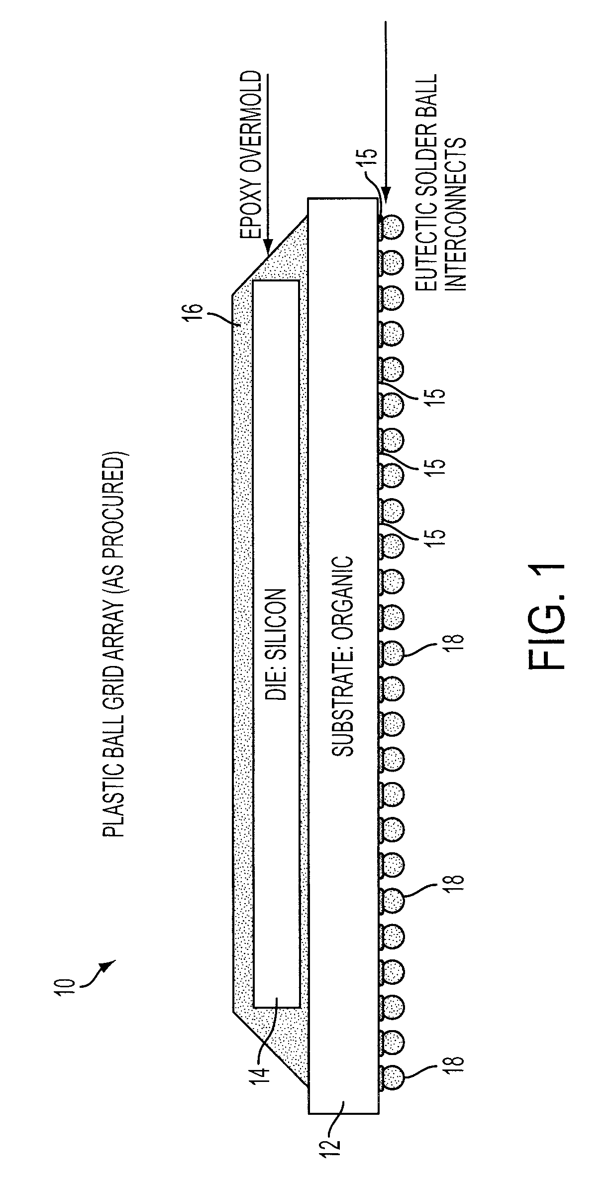
[0026]FIG. 1 is a plastic ball grid array 10 as procured which, in this example, includes an organic substrate 12, a silicon die 14, an epoxy overmold 16 and SnPb or Pb free solder ball interconnects 18 along the bottom. The die is attached to the substrate with either wire bonds or C4 interconnects. The PBGA comes from the supplier with SnPb or Pb free solder balls. In cases where the mismatch of thermal expansions between the PBGA and printed wiring board are excessive, it would be desirable for the user to add columns to provide additional strain relief, but due to warping of the PBGA when exposed to high temperatures, this cann...


PUM

PropertyMeasurementUnit
temperatureaaaaaaaaaa
stiffnessaaaaaaaaaa
perimeteraaaaaaaaaa

Abstract

A method and product which provides a thin metal or ceramic plate to the top of a plastic grid array (PGA) as a stiffener to maintain its flatness over temperature during a column attach process, and the columns are used for attachment to circuit boards or other circuit devices. These may be constructed in this manner initially or may be retrofitted plastic ball grid arrays from which the solder balls are removed and, the stiffener is attached to the top, and the solder columns have been added to replace the solder balls. The stiffener is a bonded thin metal or ceramic plate attached to the top of the PGA to maintain its flatness over temperature during the column attach process. An aluminum plate bonded to the top of a PGA results in a significant reduction in warping during a temperature cycle. This allows attachment of solder columns to the PBGA. The high melt solder columns are attached to an area array pattern on the PBGA substrate. This array is typically either a solid or perimeter grid. It is critical that the ends of the solder columns opposite the ends attached to the substrate align precisely with the matching grid of solder pads on the printed wiring board. The purpose of the stiffening plate is to maintain the flatness of the PBGA during the process of attaching the columns to the substrate as well as attaching the component to the printed wiring board such that the columns maintain their alignment over this temperature range.

Description

FIELD OF THE INVENTION[0001]This invention relates generally to electronic packaging assemblies, and more particularly, to grid array packages that are surface mounted on printed wiring boards.BACKGROUND OF THE INVENTION[0002]U.S. Pat. No. 5,972,738 is for a PBGA Stiffener Package which includes a stiffener ring and a stiffener fixture. The stiffener ring and PBGA member are essentially coplanar to less than 8 mils and a top plate is placed on top of the PBGA member and the ring and member are secured together tightly.[0003]U.S. Pat. No. 6,475,327 for attachment of a stiff heat spreader for fabricating a cavity down plastic chip carrier where there is a stiff heat spreader element and first and second bonding sheets are used and the second sheet is used to bond a circuit substrate and the stiff heat spreader element.[0004]U.S. Pat. No. 6,020,221 is for a process for manufacturing a semiconductor device having a stiffener member which is attachable to the substrate.[0005]U.S. Pat. No...

Claims


Application Information

Patent Timeline
Patent Type & Authority Patents(United States)
IPC IPC(8): H01L21/00
CPCB23K3/0623H01L23/16H01L23/49833B23K2201/40H01L23/3121H01L23/49811H01L23/49816H01L24/16H01L24/48H01L2924/10253H01L2924/10329H01L2924/15311H01L2924/15312H01L2924/3025H01L2924/3511H01L2224/48H01L2224/45147H01L2924/00H01L24/45H01L2924/181B23K2101/40H01L2924/00014H01L2924/00012
Inventor DANDO, III, CHARLES H.GONYA, STEPHEN G.MURPHY, WILLIAM E.
Owner LOCKHEED MARTIN CORP
Learn More