Droplet discharging head, image forming apparatus, and film forming apparatus

a technology of droplet and image forming, which is applied in the direction of piezoelectric/electrostrictive/magnetostrictive devices, piezoelectric/electrostriction/magnetostriction machines, piezoelectric/electrostrictive/magnetostriction machines, etc., can solve the problem of non-uniform shape of piezoelectric elements, improve the uniform shape of piezoelectric elements, improve the accuracy of liquid material dis

Inactive Publication Date: 2010-09-28
SEIKO EPSON CORP
View PDF22 Cites 0 Cited by
  • Summary
  • Abstract
  • Description
  • Claims
  • Application Information

AI Technical Summary

Benefits of technology

[0006]An advantage of the invention is to provide a droplet discharging head, an image forming apparatus, and a film forming apparatus that improve the uniformity of the shape of a piezoelectric element and thereby improve the accuracy of discharging of a liquid material.
[0007]A droplet discharging head according to a first aspect of the invention includes a diaphragm, a fixing plate, and a piezoelectric element. The piezoelectric element includes a first electrode, a second electrode, a piezoelectric body layer interposed between the first and second electrodes, a first internal electrode extending from the first electrode between the first and second electrodes, and a second internal electrode extending from the second electrode between the first and second electrodes. At least a part of a first end face of the piezoelectric element is in contact with the diaphragm. The first end face includes a first end of the first electrode, a first end of the second electrode, and a first end of the piezoelectric body layer. At least a part of a second end face of the piezoelectric element is in contact with the fixing plate. The second end face includes a second end of the first electrode and a second end of the piezoelectric body layer. At least a part of the first end of the piezoelectric body layer lies between the diaphragm and the first end of the second electrode. At least a part of the second end of the piezoelectric body layer lies between the fixing plate and a second end of the second electrode. The piezoelectric body layer includes an active layer that overlaps both the first and second internal electrodes, a first inactive layer that overlaps only the first internal electrode, and a second inactive layer that overlaps only the second internal electrode. A thickness of the second inactive layer between the second electrode and the active layer is larger than a thickness of the first inactive layer between the first electrode and the active layer. Consequently, it is possible to improve the uniformity of the shape of the piezoelectric element at the time of extension / contraction of the piezoelectric element and thereby to improve the accuracy of discharging of a liquid material.
[0008]A droplet discharging head according to a second aspect of the invention includes a diaphragm, a fixing plate, and a piezoelectric element. The piezoelectric element includes a first electrode, a second electrode, and a piezoelectric body layer interposed between the first and second electrodes. At least a part of a first end face of the piezoelectric element is in contact with the diaphragm. The first end face includes a first end of the second electrode and a first end of the piezoelectric body layer. At least a part of a second end face of the piezoelectric element is in contact with the fixing plate. The second end face includes a second end of the second electrode and a second end of the piezoelectric body layer. The diaphragm is in contact with the first end of the second electrode. At least a part of the first end of the piezoelectric body layer lies between the fixing plate and the second end of the second electrode. Consequently, it is possible to improve the uniformity of the shape of the piezoelectric element at the time of extension / contraction of the piezoelectric element and thereby to improve the accuracy of discharging of a liquid material.
[0009]A droplet discharging head according to a third aspect of the invention includes a diaphragm, a fixing plate, and a piezoelectric element. The piezoelectric element includes a first electrode, a second electrode, and a piezoelectric body layer interposed between the first and second electrodes. At least a part of a first end face of the piezoelectric element is in contact with the diaphragm. The first end face includes a first end of the first electrode and a first end of the piezoelectric body layer. At least a part of a second end face of the piezoelectric element is in contact with the fixing plate. The second end face includes a second end of the piezoelectric body layer. At least a part of the first end of the piezoelectric body layer lies between the diaphragm and the first end of the first electrode. Consequently, it is possible to improve the uniformity of the shape of the piezoelectric element at the time of extension / contraction of the piezoelectric element and thereby to improve the accuracy of discharging of a liquid material.
[0010]A droplet discharging head according to a fourth aspect of the invention includes a diaphragm, a fixing plate, and a piezoelectric element. The piezoelectric element includes a first electrode, a second electrode, and a piezoelectric body layer interposed between the first and second electrodes. At least a part of a first end face of the piezoelectric element is in contact with the diaphragm. The first end face includes a first end of the second electrode and a first end of the piezoelectric body layer. At least a part of a second end face of the piezoelectric element is in contact with the fixing plate. The second end face includes a second end of the piezoelectric body layer. At least a part of the first end of the piezoelectric body layer lies between the diaphragm and the first end of the second electrode. Consequently, it is possible to improve the uniformity of the shape of a piezoelectric element at the time of extension / contraction of the piezoelectric element and thereby to improve the accuracy of discharging of a liquid material.
[0011]In the droplet discharging head according to the fourth aspect of the invention, the first end face of the piezoelectric element preferably includes a first end of the first electrode. At least a part of the first end of the piezoelectric body layer preferably lies between the diaphragm and a first end of the first electrode. Consequently, it is possible to increase flexibility in disposition of the piezoelectric element and thereby, for example, to design a finer head.

Problems solved by technology

However, when a conductive diaphragm is used, a short circuit occurs on a side of the piezoelectric element that is joined to the diaphragm.
Additionally, providing a notch in a portion of the piezoelectric element may make the shape of the piezoelectric element nonuniform when electrostriction occurs.

Method used


Image

  • Droplet discharging head, image forming apparatus, and film forming apparatus
  • Droplet discharging head, image forming apparatus, and film forming apparatus
  • Droplet discharging head, image forming apparatus, and film forming apparatus

Examples


first embodiment

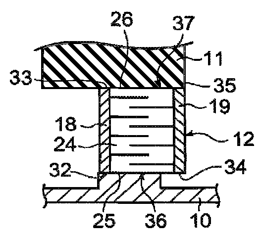
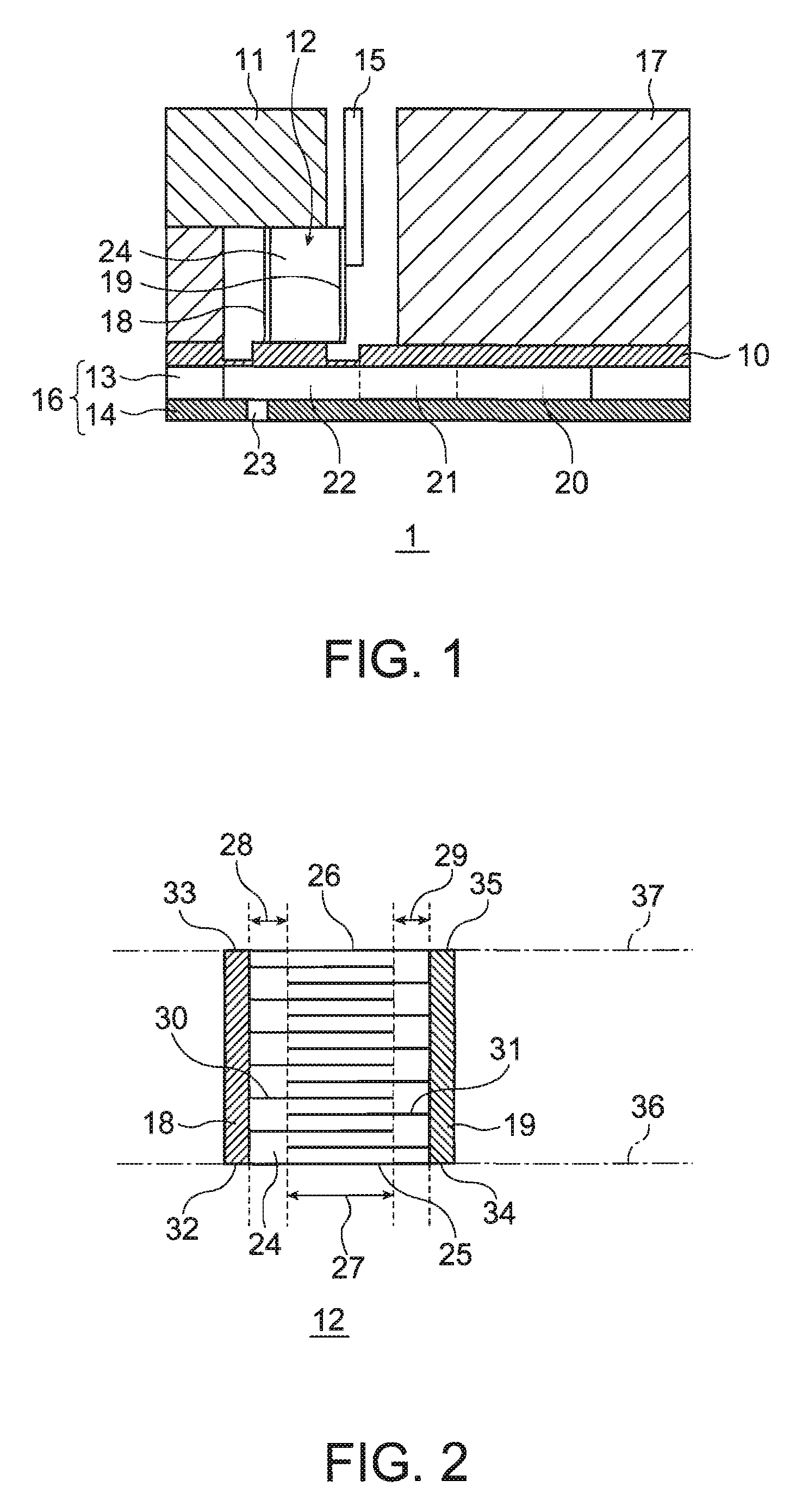
[0034]FIG. 1 is a schematic sectional view of a droplet discharging head according to a first embodiment. A droplet discharging head 1 shown in FIG. 1 includes a diaphragm 10, a fixing plate 11, a piezoelectric element 12, a flow channel substrate 13, a nozzle plate 14, a printed board 15, and a frame 17.

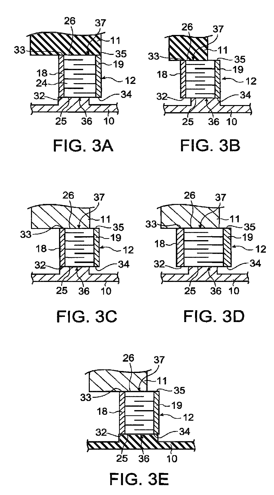
[0035]The diaphragm 10 is formed of, for example, a metal plate made of nickel or the like. As shown in the drawing, a portion of the diaphragm 10 that is in contact with the piezoelectric element 12 is separated from the other portions of the diaphragm 10, taking the shape of an island. Provided around the separated portion (protrusion) is a thin film. The protrusion and the other portions of the diaphragm 10 are integrated with the thin film therebetween. The diaphragm 10 may also be formed of a multilayer substrate including a metal plate and a resin plate.

[0036]The fixing plate 11 is a member that extends in a direction perpendicular to the paper surface on which FIG. 1 is drawn...

second embodiment

[0058]FIG. 5 is an oblique perspective view showing a film forming apparatus that is one form of a droplet discharging apparatus.

[0059]As shown in FIG. 5, a film forming apparatus 50 according to this embodiment discharges a function liquid as droplets and forms a film made of the function liquid on a substrate W. The film forming apparatus 50 includes a stage 54 on which the substrate W is placed, and a head unit 51 that has a plurality of droplet discharging heads to discharge the function liquid as droplets onto the placed substrate W.

[0060]The film forming apparatus 50 also includes an X direction guide shaft 52 for driving the head unit 51 in a subscanning direction (X direction), and an X direction drive motor 53 for rotating the X direction guide shaft 52. The film forming apparatus 50 also includes a Y direction guide shaft 55 for guiding the stage 54 in a main scanning direction (Y direction), and a Y direction drive motor 56 that rotates while engaging the Y direction guid...


PUM


Abstract

A droplet discharging head, includes a diaphragm, a fixing plate, and a piezoelectric element. The piezoelectric element includes a first electrode, a second electrode, a piezoelectric body layer interposed between the first and second electrodes, a first internal electrode extending from the first electrode between the first, and second electrodes, and a second internal electrode extending from the second electrode between the first and second electrodes. At least a part of a first end face of the piezoelectric element is in contact with the diaphragm. The first end face includes a first end of the first electrode, a first end of the second electrode, and a first end of the piezoelectric Body. The piezoelectric body layer includes an active layer that overlaps both the first and second internal electrodes, a first inactive layer that overlaps only the first internal electrode, and a second inactive layer that overlaps only the second internal electrode. A thickness of the second inactive layer between the second electrode and the active layer is larger than a thickness of the first inactive layer between the first electrode and the active layer.

Description

BACKGROUND[0001]1. Technical Field[0002]Several aspects of the present invention relate to a droplet discharging head, an image forming apparatus, and a film forming apparatus.[0003]2. Related Art[0004]As the industrial application of inkjet technologies proceeds, droplet discharging heads are required to discharge more minute droplets in order to form a finer wiring pattern or the like. In order to make droplets to be discharged more minute, it is necessary to use an actuator that can be driven by high frequency signals and ensure necessary and sufficient displacements (see JP-A-2003-92437 as a related art example). To meet such necessity, for example, displacements of a piezoelectric element in the d33 direction can be effectively used.[0005]In the aforementioned related art example, a notch is provided in a portion of a side of the piezoelectric element that is joined to a fixing plate for an individual electrode. This prevents a short circuit from occurring on the side of the pi...

Claims


Application Information

Patent Timeline
Patent Type & Authority Patents(United States)
IPC IPC(8): H01L41/08
CPCB41J2/14274H01L41/083H10N30/50B41J2/045B41J2/01
Inventor TAKAHASHI, HAYATO
Owner SEIKO EPSON CORP
Why Eureka
Try Eureka