Fluorescence tomography using line-by-line forward model

a forward model and fluorescence technology, applied in the field of fluorescence optical imaging, can solve the problems of complicated problem of acquiring an accurate image of the voi, the heterogeneity of optical properties associated with the non-trivial anatomy of the animal cannot be ignored, and the problem of increasing the computational burden, so as to reduce the scattering coefficient, improve the calculation, and increase the computational burden

Inactive Publication Date: 2010-10-12
SOFTSCAN HEALTHCARE GROUP
View PDF4 Cites 6 Cited by
  • Summary
  • Abstract
  • Description
  • Claims
  • Application Information

AI Technical Summary

Benefits of technology

[0007]In accordance with the present invention, a fluorescence optical tomography method and system are provided that use values for absorption and reduced scattering coefficients μa and μs′ determined for each source / detector pair to improve the calculation using the photon migration model without significantly increasing the computational burden relative to the use of global estimates for μa and μs′. The tomography system produces an image of a volume of interest indicative of location and number density of fluorophores embedded therein, and relies on optical scanning of the volume at a plurality of source / detector geometries. An optical source, which may include multiple discrete sources, generates an optical signal at an excitation wavelength that interacts with the fluorophores to cause fluorescence therefrom at a fluorescence wavelength. A time resolved detector may be used to detect the excitation wavelength and provide an input to a determinator that determines separately, for each of the source / detector geometries, an absorption coefficient and a reduced scattering coefficient. Alternatively, predetermined information about the spatial distribution of optical properties in the sample of interest (coming from such means as optical imaging or multimodal imaging) may be provided as an input to a determinator that determines separately, for each of the source / detector geometries, an effective absorption coefficient and an effective reduced scattering coefficient. A photon migration model calculator receives the absorption and reduced scattering coefficients and uses them in calculating a forward model which gives the approximate relative contribution of each voxel within the volume of interest to the fluorescence signal.

Problems solved by technology

For in vivo imaging however, the optical property heterogeneities associated with the non-trivial anatomy of the animal cannot simply be neglected.
To that effect, more sophisticated (and time-consuming) methods exist where photon propagation is actually computed using the a priori information related to organs and tissues (spatial distribution and optical properties).
For a heterogeneous sample, such as a small animal, the variations in composition of the sample from one location to another complicate the problem of acquiring an accurate image of the VOI.
However, such an assumption is crude, and is particularly ineffective when performing imaging in vivo, and the alternative of using information gathered from another modality may be unattractive as it significantly complicates the imaging process.

Method used


Image

  • Fluorescence tomography using line-by-line forward model
  • Fluorescence tomography using line-by-line forward model
  • Fluorescence tomography using line-by-line forward model

Examples


Embodiment Construction

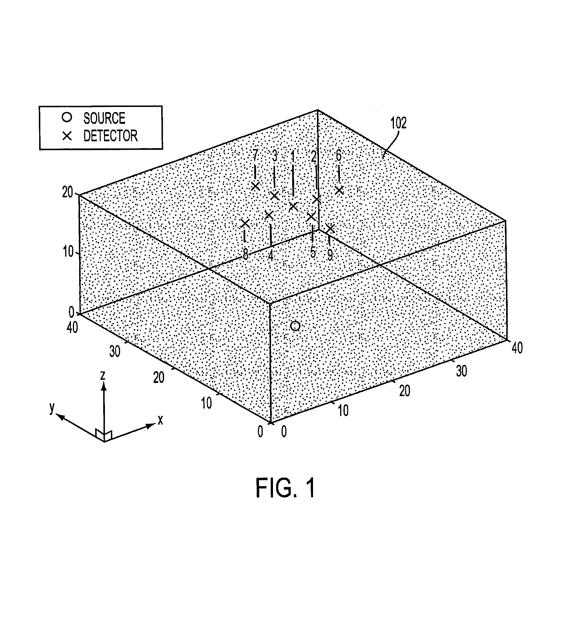
[0015]Shown in FIG. 1 is a schematic image of a sample 102 comprising a volume of interest (VOI) which might be selected for examination using the present invention. For ease of description, the VOI shown in the figure has the shape of a right angle parallelepiped, but those skilled in the art will recognize that the actual shape may be different. In this example, the volume is to be scanned using one source location (indicated by a “O” in the figure) and nine detector locations (each indicated by an “X”) in the figure. As shown, the detectors are arranged in a “cross-shape” geometry, and the detectors and the source are positioned, respectively, on opposite sides of the sample. Relative to the Cartesian coordinate system shown in the figure, tomographic data is collected by raster-scanning this configuration over a two-dimensional region of interest in the x-y plane.

[0016]The construction of an optical fluorescence model using the present invention does not use values for absorptio...


PUM


Abstract

A fluorescence optical tomography system and method uses a photon migration model calculator for which absorption and reduced scattering coefficient values are determined for each source / detector pair. The coefficient values may be determined by measurement, in which a time resolved detector detects the excitation wavelength and generates temporal point spread functions from which the coefficient values are found. Alternatively, the coefficient values may be determined by calculating them from a dataset containing a spatial distribution of absorption and reduced scattering coefficients in a volume of interest. The fluorescence detection may be continuous wave, time resolved, or a combination of the two. An estimator uses a detected fluorescence signal and an estimated fluorescence signal to estimate the image values.

Description

FIELD OF THE INVENTION[0001]This invention relates generally to the field of fluorescence optical imaging of turbid media.BACKGROUND OF THE INVENTION[0002]Imaging of mammalian tissues has been used extensively to obtain information on the internal structures as well as on the biodistribution of molecules. This information can of course be utilized for diagnosis purposes. Several techniques based on different physical principles are currently available to obtain images that encompass a broad range of spatio-temporal resolution. Such techniques include Magnetic Resonance Imaging (MRI), Positron Emission Tomography (PET), single-photon emission computed tomography (SPECT), X-ray, ultrasound and, now emerging, optical imaging.[0003]In optical imaging, three approaches have been used to generate the optical data necessary to reconstruct images of volume of interest (VOI). The continuous wave (CW) technique uses a continuous wave light source and allows the measurement of light attenuatio...

Claims


Application Information

Patent Timeline
Patent Type & Authority Patents(United States)
IPC IPC(8): G01J3/30
CPCG01N21/4795G01N21/6456
Inventor FORTIER, SIMONLEBLOND, FREDERIC
Owner SOFTSCAN HEALTHCARE GROUP
Why Eureka
Try Eureka