
LED apparatus with temperature control function

a technology of temperature control and led devices, which is applied in the direction of lighting and heating devices, process and machine control, instruments, etc., can solve the problems of bringing in-rush current to the system, and achieve the effect of flexible manufacturing

Inactive Publication Date: 2010-10-19
POLYTRONICS TECH
View PDF5 Cites 16 Cited by
  • Summary
  • Abstract
  • Description
  • Claims
  • Application Information

AI Technical Summary

Benefits of technology

The PTC device effectively prevents thermal runaway, maintains LED performance by regulating temperature and current, and enhances heat dissipation efficiency, ensuring prolonged LED lifespan and reliability.

Problems solved by technology

In an electric circuit, many incidents, such as hot plug, on-off switch, power surge, etc., could bring in-rush current to the system.

Method used


Image

  • LED apparatus with temperature control function
  • LED apparatus with temperature control function
  • LED apparatus with temperature control function

Examples


Embodiment Construction

[0027]The present invention will be explained with the appended drawings to clearly disclose the technical characteristics of the present invention.

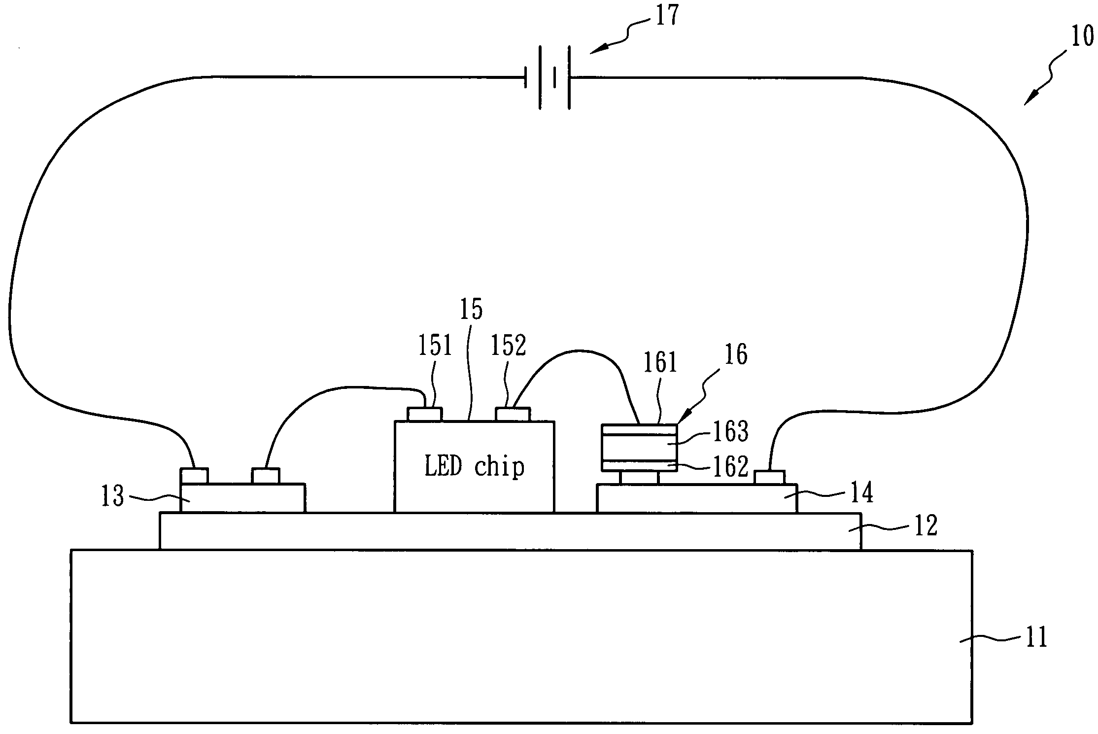
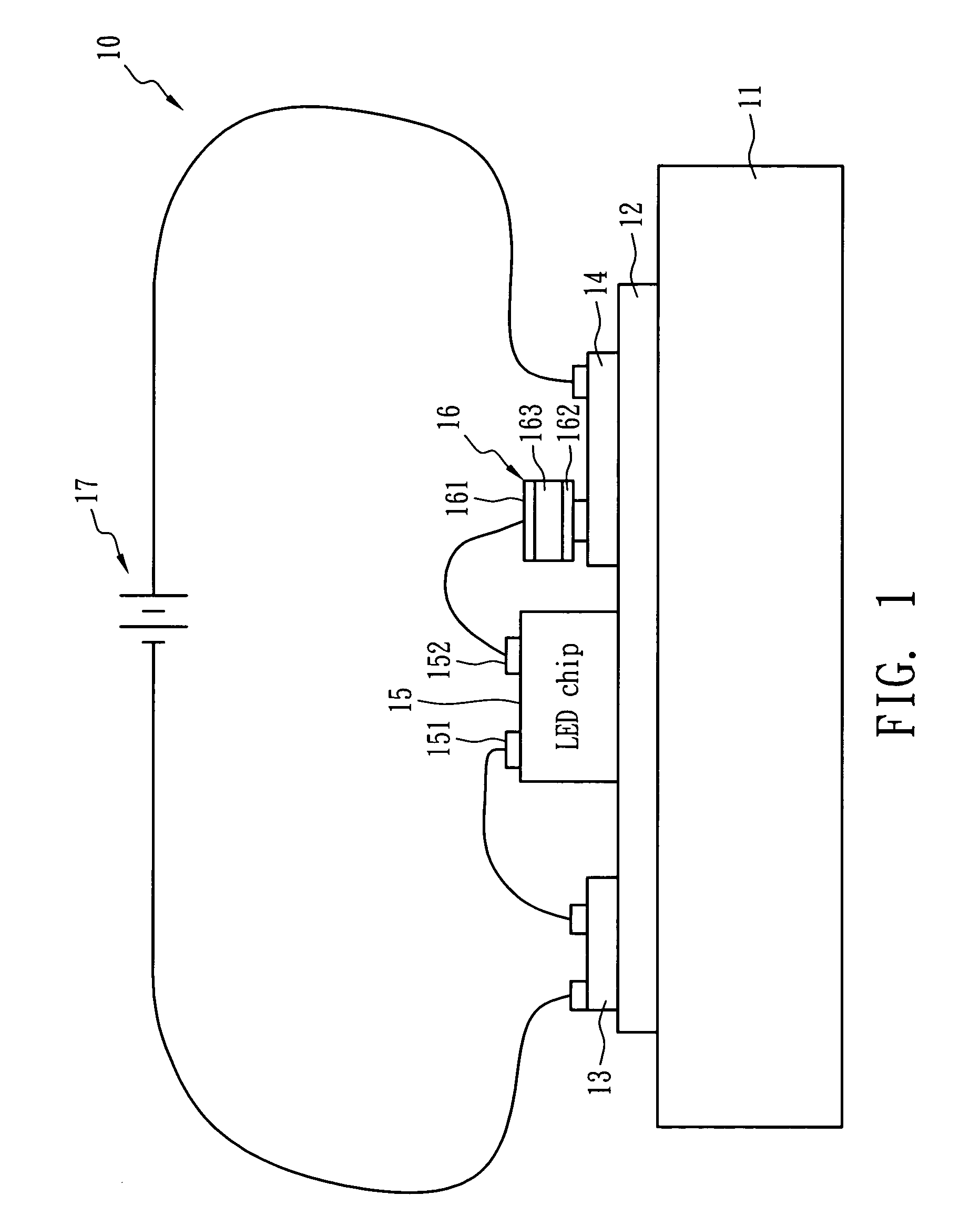
[0028]FIG. 1 illustrates an LED apparatus with temperature control function in accordance with an embodiment of the present invention. An LED apparatus 10 comprises a heat dissipation plate 11, a heat conductive layer 12, a first electrode 13, a second electrode 14, an LED chip 15 and a temperature control device 16. The LED chip 15, the first electrode 13 and the second electrode 14 are disposed on a side of the heat conductive layer 12, and the other side of the heat conductive layer 12 is in contact with the heat dissipation plate 11 so as to dissipate the heat of the LED chip 15. In short, the heat conductive layer 12 and heat dissipation plate 11 are used for carrying the LED chip 15 and for heat dissipation while the LED chip 15 illuminates.

[0029]The distance between the temperature control device 16 and the LED chip 15 is less tha...


PUM


Abstract

An LED apparatus with temperature self-regulating, over-temperature protection, and over-current protection function comprises an LED chip, a heat dissipation plate, a heat conductive layer and a temperature control device. The heat dissipation and the heat conductive layer disposed thereon carry the LED chip and dissipate the heat generated from the LED chip that is connected to an electric power source for luminance. The temperature control device exhibiting PTC behavior is electrically connected between the LED chip and the electric power source in series, and the distance between the LED chip and the temperature control device is less than 3 cm. The heat conductive layer can consist of polymeric dielectric material and has a heat conduction coefficient larger than 1.0 W / mK at 25° C.

Description

BACKGROUND OF THE INVENTION[0001](A) Field of the Invention[0002]The present invention is related to an LED (light emitting diode) apparatus, more specifically, to an LED apparatus having temperature control functions.[0003](B) Description of the Related Art[0004]In recent years, white light LED is an attractive new product with increasing importance around the world. It has the advantages of small volume, low power consumption, long lifetime and quick response, and can solve many problems that exist with an incandescent lamp.[0005]In view of the consensus of Japan, European countries, and the U.S. on power saving and environmental protection, the countries are actively developing white light LED as the luminance source for this century. In addition, if all incandescent lamps are replaced with white light LEDs, electric power consumption can be diminished and carbon dioxide (CO2) generation can be decreased so as to reduce the greenhouse effect. Accordingly, European countries, the ...

Claims


Application Information

Patent Timeline
Patent Type & Authority Patents(United States)
IPC IPC(8): H01C3/04
CPCH05B33/0821H05B33/0854H05B33/089H01L25/167Y02B20/341H01L2224/48137H01L2224/48091H01L2924/00014H01L2224/73265H05B45/40Y02B20/30H05B45/18H05B45/56
Inventor WANG, SHAU CHEWYU, JYH MING
Owner POLYTRONICS TECH
Learn More