Method for fabrication of hermetic electrical conductor feedthroughs

a technology of electrical conductors and feedthroughs, which is applied in the direction of conductive pattern formation, coupling device connections, therapy, etc., can solve the problems of epoxy being toxic to body tissue, affecting the performance of the product, so as to improve the bond strength, facilitate light adhesion, and complicate the fabrication process

Inactive Publication Date: 2010-10-26
NEWSOUTH INNOVATIONS PTY LTD
View PDF9 Cites 29 Cited by
  • Summary
  • Abstract
  • Description
  • Claims
  • Application Information

AI Technical Summary

Benefits of technology

[0005]In 1977, de Bruin and colleagues (U.S. Pat. No. 4,050,956) patented a technique for the purpose of joining two or more ceramic bodies. The present invention, while using the natural phenomenon of bonding described within de Bruin's patent, pertains more specifically to the utilization of the aforementioned natural phenomenon of bonding rather than the bonding itself. A principal advantage of the present invention is, by way of the planar and layered structuring, the ability to promote the formation of bonding (mechanical, chemical or otherwise) between the insulator and the metallic conductor thereby improving the hermeticity. This is in contrast to existing methods wherein wires are individually cast into an insulating material in order to form an assembly. As such, no mechanism exists to promote bonding. Indeed in such cases the tendency towards the aforementioned formation of bonding is reduced or eliminated, with the hermeticity achieved only by way of tight dimensions.
[0006]Despite the differential expansion and contraction properties of platinum and ceramic, Researchers Allen and Borbidge published work in 1983 that identified that, through the application of compressive force during the sintering process, an improved bond strength can be created between platinum and ceramic (as well as other material combinations). The aforementioned fabrication method with conductors oriented perpendicular to the wall of the hermetic chamber does not lend itself to the application of pressure unless said pressure can be applied in all directions at the same time. While isostatic pressing during sintering is indeed possible, this approach substantially complicates the fabrication procedure thus highlighting one of the advantages of the present invention.SUMMARY OF THE INVENTION
[0007]Accordingly, in one embodiment, the present invention proposes that a stacked assembly be constructed comprising a substrate material of previously sintered and densified ceramic (Al2O3 for example) covered with a thin layer of slurry comprised of ceramic particulate (for example, of the same chemical composition as the substrate) and, if necessary, an appropriate binder, followed by a pre-patterned layer of foil (e.g. Pt), then by a second layer of slurry similar to the first, and topped with a second previously sintered and densified ceramic (for example, of the same material composition as the substrate). Said assembly is then placed in a heated environment wherein forces longitudinal to the stacked structure can be applied, and brought to a temperature where recrystallization (sintering) of the slurry occurs. The sintering process binds the slurry to the previously sintered and densified ceramic. Elevated temperature in conjunction with the longitudinal forces (applied or intrinsic) promotes bonding of the slurry to the pre-patterned layer of foil (e.g. Pt). Following cooling, the assembly comprises an upper surface and a lower surface. One or more perpendicular excavations in pre-determined locations are made on the upper surface to a depth sufficient to expose the surface or some part of the foil (e.g. Pt). Corresponding, but not necessarily co-axial excavations can be made on the lower surface. An appropriate material may be filled into said excavations. This may be any appropriate conductor including platinum, and may be applied by any appropriate method including electroplating.
[0008]An alternative embodiment of the invention describes that the foregoing ceramic components of the assembly be made in whole or in part from unsintered ceramic slurry or particulate. In this embodiment, an organic binder may be used in order to promote light adhesion between ceramic particles so that a structure may be formed and maintained prior to sintering.
[0009]A preferred embodiment of the invention describes that the pre-patterned layer of foil be shaped such that all areas of said foil are electrically connected so as to facilitate electroplating with one electrical connection to said pre-patterned layer of foil. In this embodiment, an appropriate means of isolating each individual conductor after electroplating would be incorporated, for example, by way of removing a portion or portions of the foil that introduce short circuits between conductors, or by severing short circuits through the passage of current sufficient to permanently break the continuity.
[0010]A further alternative embodiment of the invention describes a means for incorporation of an electrode array (or part thereof) within said pre-patterned layer of foil with none, all, or part of said electrode array patterned after sintering. Through this embodiment, interconnections need not be made to the electrode array as these interconnections are incorporated within the patterning.

Problems solved by technology

Further, as the second wire exits the pipe, it must not allow the contents of the pipe to leak out.
For instance, the corrosive nature of body fluids would substantially limit the materials that could be used as an electrical conductor.
Moreover, epoxy may be toxic to body tissue or otherwise be damaged, over time, by the chemical composition of the fluids in which it is immersed.
Of particular concern in body implantable electronics is corrosion of active electronics within said implant.
If the level of hermeticity achieved by the hermetic feedthrough is insufficient to prevent passage of water and other molecules into the implant, it may lead to a corrosive environment being formed within the implant which, eventually, can cause device failure through degradation of the electronics.
As such, a number of limitations must be applied to body-implantable hermetic feedthroughs.
Second, the longevity of the hermetic feedthrough must be such that it exceeds the intended lifetime of the implant, which is often the lifetime of the implant recipient.
Third, the level of hermeticity of the feedthrough must be such that, over the lifetime of the implant, the moisture content within the implant must not be allowed to reach a level at which condensation (and therefore corrosion) may occur.
Given these limitations, very few options are afforded to designers of long-term medical implants containing active electronics and so the state of the art of hermetic feedthroughs remains rather limited.
Combine the limited list of materials with those which are capable of forming a long-term hermetic seal, designers are left with few options.
This potentially compromises the hermetic integrity of the assembly.
Beyond a few tens of conductors within the feedthrough, the reliability of this method is compromised to such an extent that it is no longer practical and alternatives —such as those disclosed in the present invention—are necessary when approaching the design of, for example, a visual prosthesis for the blind such as that disclosed by the present inventor in U.S. Pat. No. 6,458,157.

Method used


Image

  • Method for fabrication of hermetic electrical conductor feedthroughs
  • Method for fabrication of hermetic electrical conductor feedthroughs
  • Method for fabrication of hermetic electrical conductor feedthroughs

Examples


Embodiment Construction

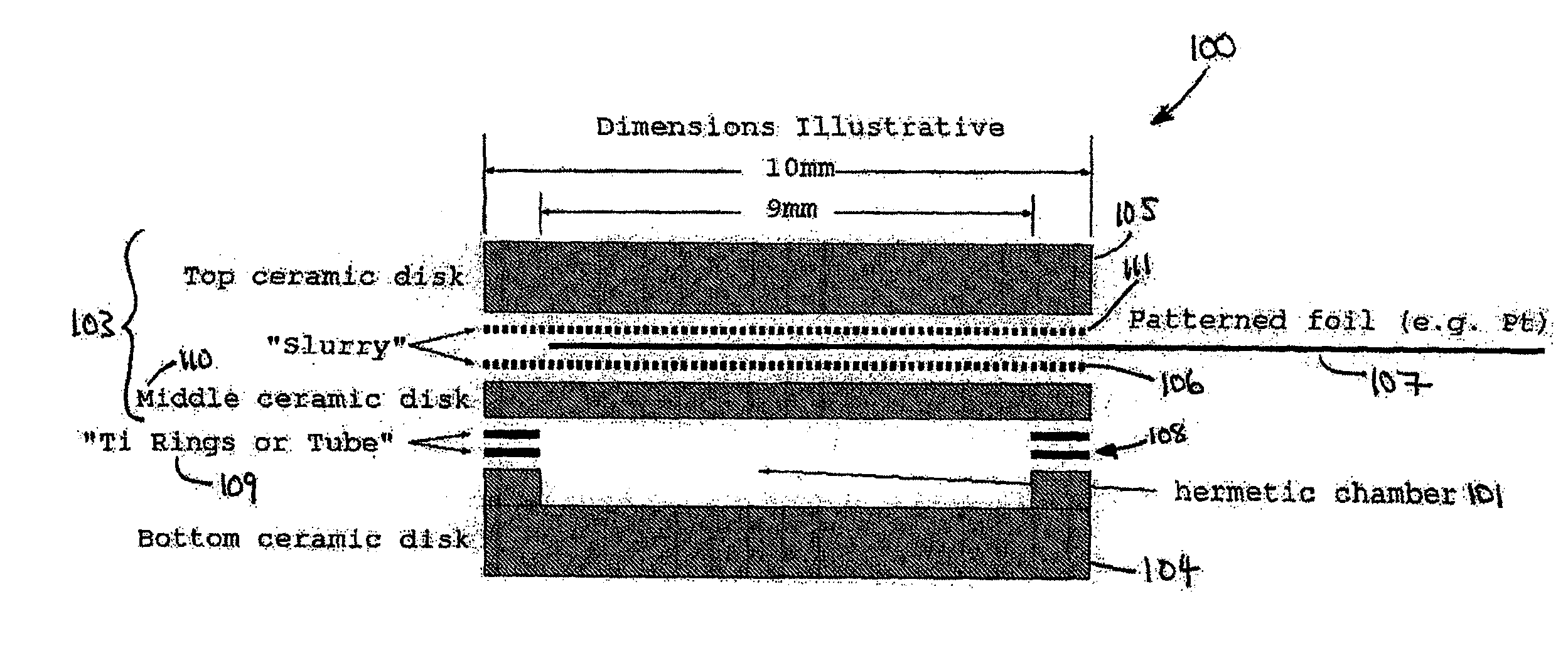
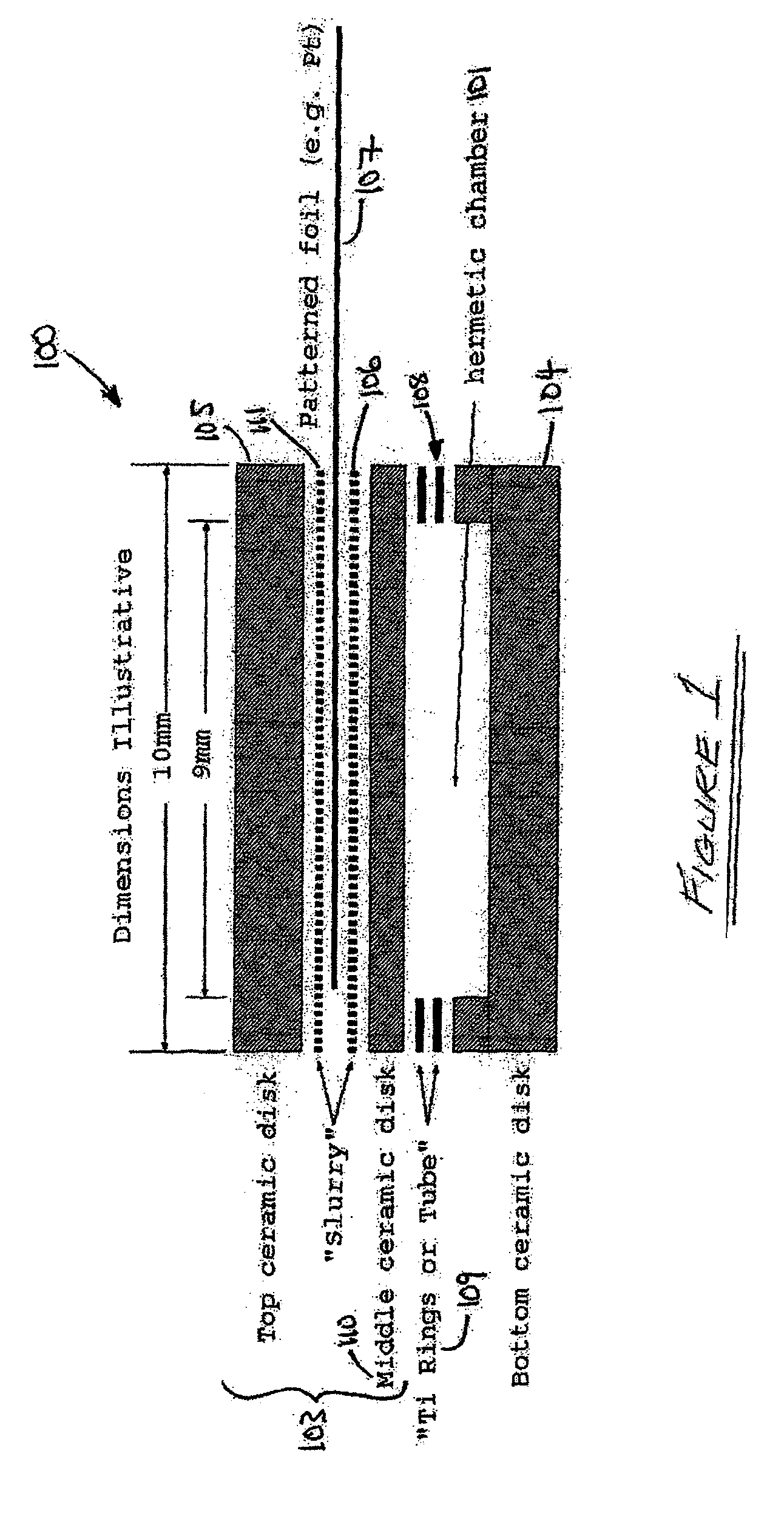
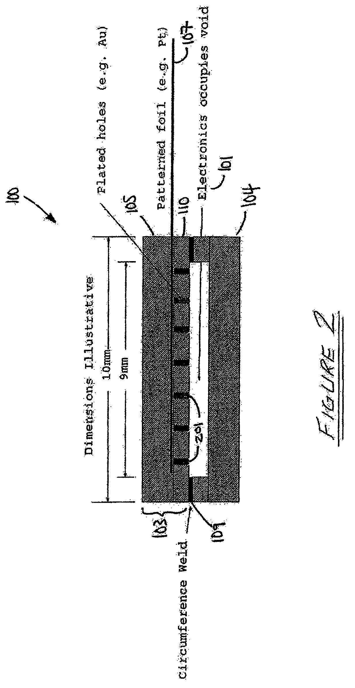
[0037]An important factor that determines the longevity of an electronic circuit is its ability to withstand damage from corrosion. Ideally, said corrosion is prevented by sealing the electronics within a chamber that is either held in vacuum, or filled with an inert gas. This chamber is termed hermetic when sealed. However, even with this precaution, diffusion of ions over the lifetime of the electronics can lead to sufficient quantities of corrosive matter such that damage to the electronics can occur. This situation is of critical importance in the manufacturing of implantable medical devices that include electronics cochlear implants, cardiac pacemakers, and other devices containing electronics that are implanted within body.

[0038]The present invention describes a methodology for an improved hermetic chamber that also allows for the transmission of single or a plurality of electrical signals through said hermetic chamber. Said hermetic chamber is comprised of an electrical insul...


PUM


Abstract

A method is disclosed for the fabrication of feedthrough devices that can transmit a single or plurality of electrical signal(s) to or from within a leak-tight (hermetic) chamber from or to the outside of said leak-tight (hermetic) chamber. The invention allows materials known to be well-tolerated within the human body such as alumina-oxide ceramic and platinum to be used as raw materials in the fabrication of body-compatible, single or multi-channel leak-tight (hermetic) feedthroughs.

Description

CROSS REFERENCE TO DISCLOSURE DOCUMENT[0001]This application is based upon Provisional Application for Patent 60 / 794,590 filed 25 Apr. 2006. Priority is claimed thereto.FIELD OF THE INVENTION[0002]The present invention is directed generally to approaches to the passage of one or more electrical signals across a leak-tight (hermetic) barrier. More specifically, the present invention is directed to the use of methods of enclosing electronics within a leak-tight (hermetic) chamber in such a way as to facilitate the passage, in either direction, of electrical signal or signals from within said leak-tight (hermetic) chamber to outside said chamber, without significantly compromising the effectiveness of the leak-tight (hermetic) chamber through the introduction of leaks.BACKGROUND OF THE INVENTION[0003]It is often the case where an electronic circuit comprised of semiconductor (and perhaps other) components must be sealed within a leak-tight chamber so as to protect it from corrosive or ...

Claims


Application Information

Patent Timeline
Patent Type & Authority Patents(United States)
IPC IPC(8): H01R43/00
CPCA61N1/3754H01L21/48H01R12/523C04B37/021Y10T29/49165C04B2237/343C04B2237/403H01R13/5224H05K1/0306H05K3/202Y10T29/49128Y10T29/49155Y10T29/49117Y10T29/4913Y10T29/49126Y10T29/49147
Inventor SUANING, GREGG JORGEN
Owner NEWSOUTH INNOVATIONS PTY LTD
Why Eureka
Try Eureka