Vapour compression device and method of performing an associated transcritical cycle

a technology of fluid compression and transcritical cycle, which is applied in the direction of gas cycle refrigeration machines, compression machines with non-reversible cycles, lighting and heating apparatus, etc. it can solve the problems of fluid inlet to expansion valve, fluid inlet in temperature difference, and inability to adjust the temperature difference, so as to improve cycle efficiency and reduce the irreversibility of internal heat exchangers

Inactive Publication Date: 2010-10-26
COMMISSARIAT A LENERGIE ATOMIQUE ET AUX ENERGIES ALTERNATIVES
View PDF4 Cites 15 Cited by
  • Summary
  • Abstract
  • Description
  • Claims
  • Application Information

AI Technical Summary

Benefits of technology

[0045]One object of the invention is to remedy all the above-mentioned shortcomings and has the object of providing a vapour compression device, for a transcritical fluid cycle, whereby the irreversibilities in the internal heat exchanger can be reduced so as to obtain an improved cycle efficiency, while at the same time ensuring that the refrigerant, in particular carbon dioxide, remains single-phase in the whole of the internal heat exchanger.

Problems solved by technology

However, the heat exchange is limited by the mass heat difference between the CO2 at high pressure and the CO2 at low pressure.
Firstly, the CO2 at intermediate pressure Pint, i.e. between points 10 and 4 of FIG. 2, is two-phase and its temperature is constant, which results in the cooler in a temperature difference with the CO2 at high pressure and therefore in irreversibilities.
Secondly, the fluid inlet to the expansion valve designed to perform the expansion step on the main circuit of the cycle (point 8 of the cycle of FIG. 2) can not reach the cold source temperature TF.
If this was not the case, the Coefficient Of Performance (COP) would be disadvantageous, in particular lower than the coefficient of performance obtained in an Evans-Perkins cycle as described previously.
However under such conditions, an increase of the high pressure PHP can result in a reduction of the efficiency, for on the one hand the compression work is greater, and on the other hand point 1 of the cycle moves underneath the saturator bell, i.e. under the parabola representative of the CO2 phase diagram delineating the different states (solid, liquid, gaseous) of the CO2.
A single-phase state of the fluid is therefore not possible in the whole heat exchanger 12, especially if hot source temperature TC is lower than 56° C. Above 56° C., the fluid is in fact only single-phase in heat exchanger 12, but the price to pay is an excessive energy consumption and a lesser cycle efficiency, the discharges being at temperatures that are not acceptable, i.e. that are too high, typically about 56° C. for CO2.

Method used


Image

  • Vapour compression device and method of performing an associated transcritical cycle
  • Vapour compression device and method of performing an associated transcritical cycle
  • Vapour compression device and method of performing an associated transcritical cycle

Examples


Embodiment Construction

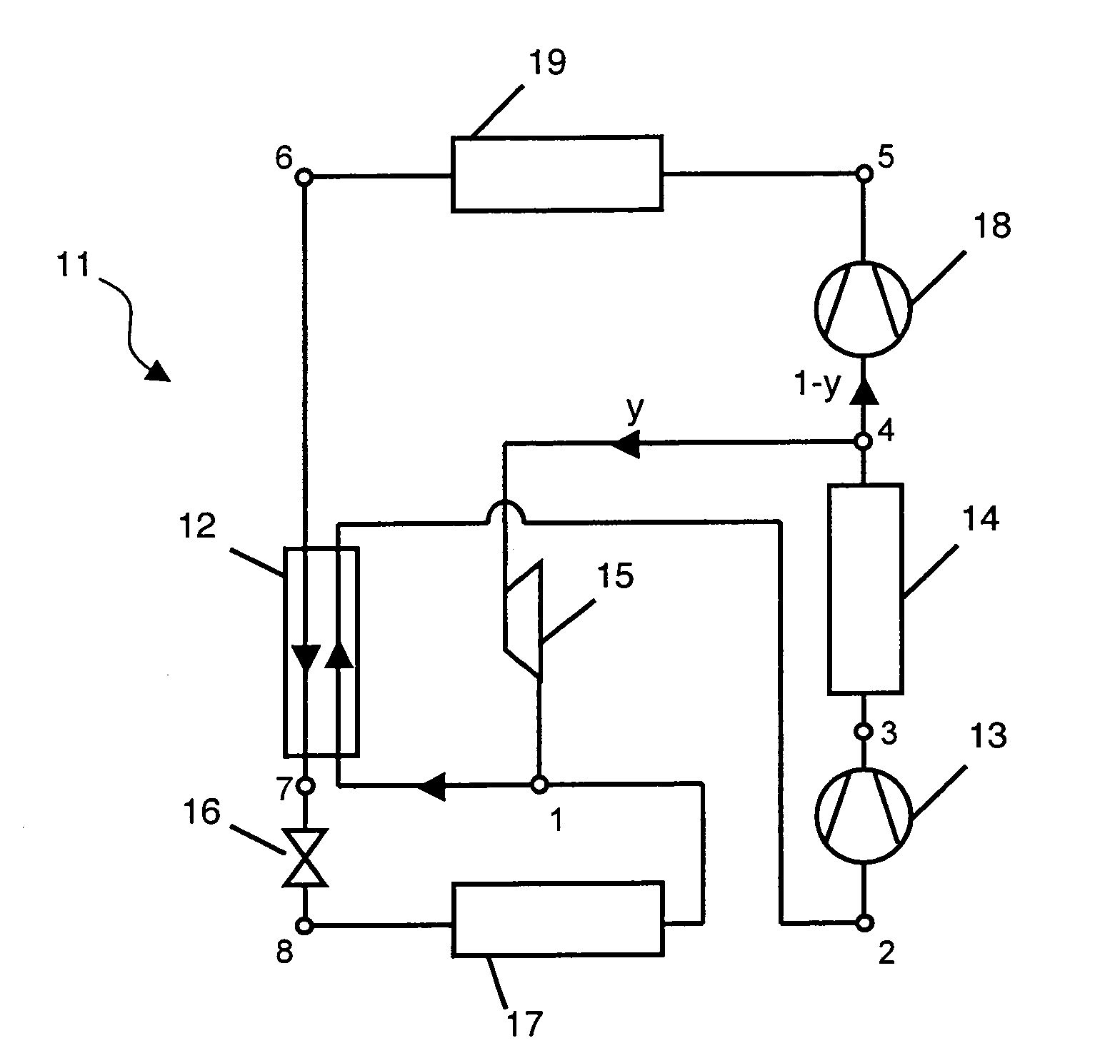
[0055]With reference to FIGS. 5 to 7, the vapour compression device 11 according to the invention (FIG. 5) concerns a new refrigeration thermodynamic cycle, i.e. a vapour compression cycle. It is in particular suitable for the use of carbon dioxide CO2 as refrigerant. The interest shown in CO2 stems from its low environmental impact with regard to the fluorinated synthetic refrigerants usually used, freons, certain of which destroy the ozone layer and others are greenhouse effect gases (generally more than a thousand times more powerful than CO2). CO2 is in addition neither toxic nor flammable.

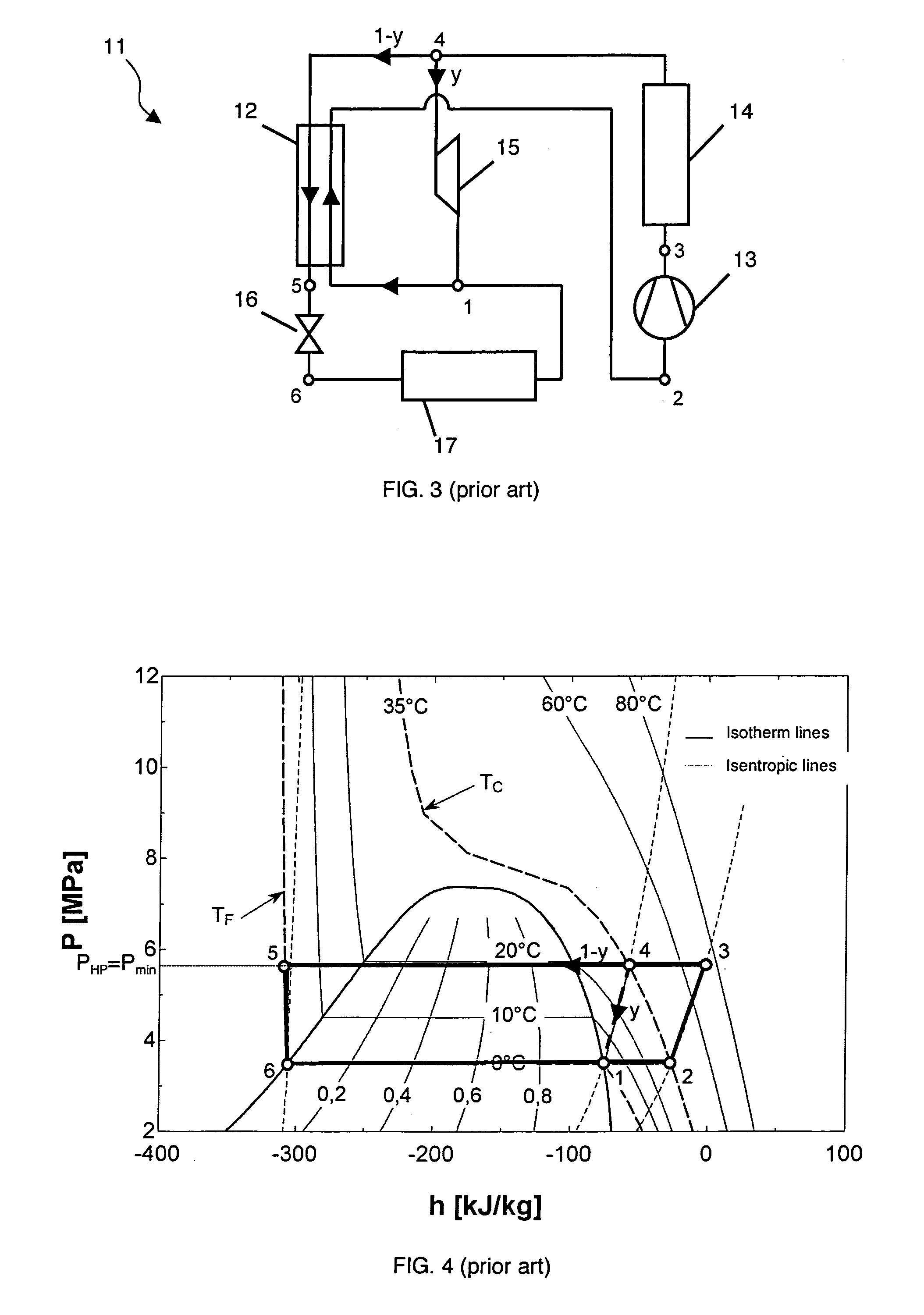
[0056]In FIG. 5, a particular embodiment of vapour compression device 11 is represented in schematic form. Device 11 differs from the device according to Meunier's cycle (FIG. 3) by the addition of a compressor 18, operating at high pressure, on the main circuit 1−y of the cycle. The new compression stage defined by high-pressure compressor 18 then requires the addition of an associated isobar...


PUM

PropertyMeasurementUnit
critical temperature Tcritaaaaaaaaaa
temperature TFaaaaaaaaaa
temperature TCaaaaaaaaaa

Abstract

A vapour compression device including an internal heat exchanger, a low-pressure compressor and an associated gas cooler, a fluid distributor separating the fluid into a main circuit of the cycle and into an auxiliary cooling circuit of the cycle, an auxiliary expansion system placed on the auxiliary cooling circuit, and a main expansion system placed on the main circuit of the cycle. The device also includes a high-pressure compressor and an associated gas cooler placed on the main circuit of the cycle. A method for performing a transcritical fluid cycle including a substantially isentropic compression step of the fluid, on the main circuit of the cycle, to reach a maximum high pressure greater than a critical pressure of the fluid, and an isobaric cooling step of the fluid to substantially reach a cold source temperature.

Description

BACKGROUND OF THE INVENTION[0001]The invention relates to a vapour compression device for a transcritical fluid cycle, comprising at least:[0002]an internal heat exchanger,[0003]a first vapour compression system connected to the outlet of the internal heat exchanger,[0004]a first isobaric cooling system connected to the outlet of the first vapour compression system,[0005]a fluid distributor placed at the outlet of first isobaric cooling system and separating the fluid into a main circuit of the cycle and an auxiliary cooling circuit of the cycle,[0006]an auxiliary expansion system placed on the auxiliary cooling circuit between the fluid distributor and the inlet of the internal heat exchanger,[0007]a main expansion system placed on the main circuit and connected to the outlet of the internal heat exchanger,[0008]an evaporator operating at low pressure placed between the outlet of the main expansion system and the inlet of the internal heat exchanger.[0009]The invention also relates...

Claims


Application Information

Patent Timeline
Patent Type & Authority Patents(United States)
IPC IPC(8): F25B41/00C01B32/40
CPCF25B1/10F25B9/008F25B40/00F25B9/06F25B2309/061
Inventor DUCOULOMBIER, MAXIMECOLASSON, STEPHANE
Owner COMMISSARIAT A LENERGIE ATOMIQUE ET AUX ENERGIES ALTERNATIVES
Why Eureka
Try Eureka