Polymerizable liquid crystal composition, optical device, method of manufacturing optical device, and liquid crystal display

a technology of liquid crystal composition and polymerizable liquid crystal, which is applied in the direction of liquid crystal compositions, instruments, chemistry apparatuses and processes, etc., can solve the problems of easy change of retardation layer, insufficient heat resistance of retardation layer of foregoing hybrid structure, and difficulty in keeping expected characteristics, so as to improve the heat resistance of optical devices

Inactive Publication Date: 2010-11-02
JAPAN DISPLAY WEST
View PDF15 Cites 3 Cited by
  • Summary
  • Abstract
  • Description
  • Claims
  • Application Information

AI Technical Summary

Benefits of technology

[0019]According to this, by using the photopolymerization initiator represented by the general formula (1) or (2), it has been confirmed that the heat resistance of an optical device having a polymerizable liquid crystal monomer hybrid-aligned therein is improved as demonstrated in the Examples as described later.
[0022]In accordance with the foregoing embodiments according to the invention, it becomes possible to improve the heat resistance of an optical device having a polymerizable liquid crystal monomer hybrid-aligned therein. According to this, it becomes possible to provide, as a retardation layer, an optical device having a polymerizable liquid crystal monomer hybrid-aligned therein in a liquid crystal cell which is required to have heat resistance.

Problems solved by technology

However, retardation layers using a related-art polymerizable liquid crystal material, in particular retardation layers of the foregoing hybrid structure did not have sufficient heat resistance against the in-cell processing and were easily changed in the retardation by the heat treatment.
Thus, it was difficult to keep expected characteristics.

Method used


Image

  • Polymerizable liquid crystal composition, optical device, method of manufacturing optical device, and liquid crystal display
  • Polymerizable liquid crystal composition, optical device, method of manufacturing optical device, and liquid crystal display
  • Polymerizable liquid crystal composition, optical device, method of manufacturing optical device, and liquid crystal display

Examples


example 1

[0076]The following materials (1) to (5) were mixed to prepare a coating solution for forming an optical device.

(1) Polymerizable Liquid Crystal Monomer:

[0077]15 parts by weight of a compound represented by the general formula (3) wherein Y1 and Y2 are each —COO—; W1 and W2 are each —OCO—; p is 4; and q is 4.

(2) Polymerizable Liquid Crystal Monomer:

[0078]5 parts by weight of a compound represented by the following structural formula (1).

(3) Photopolymerization Initiator:

[0079]1 part by weight of IRGACURE 907 (a trade name of Ciba Specialty Chemicals) as one compound represented by the general formula (1).

(4) Fluorine Based Surfactant:

[0080]0.2 parts by weight of DMAOP (a trade name of Azmax Co., Ltd.).

(5) Solvent:

[0081]78.8 parts by weight of propylene glycol methyl ethyl ether (PGMEA).

[0082]

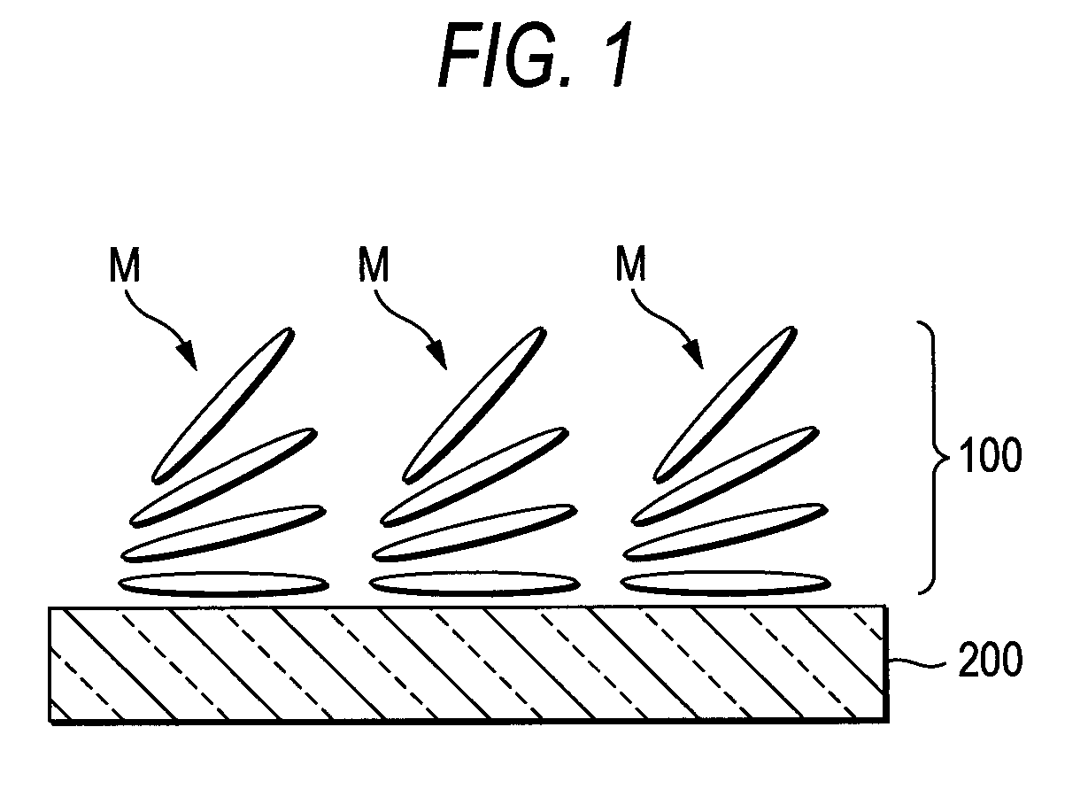
[0083]The prepared coating solution was spin coated on an alignment film AL1254 (a trade name of JSR Corporation) having been subjected to rubbing processing, thereby forming a coating film. The...

example 2

[0091]An optical device was prepared in the same manner as in Example 1, except for changing the photopolymerization initiator (3) as used in Example 1 to IRGACURE 369 (a trade name of Ciba Specialty Chemicals) as one compound represented by the general formula (2) which is characteristic in an embodiment according to the invention. As shown in the foregoing Table 1, with respect to the retardation before and after the heat resistance test, the same results as in Example 1 are revealed. According to this, it was confirmed that by using a photopolymerization initiator which is characteristic in an embodiment according to the invention, the optical device having a liquid crystal molecule hybrid-aligned therein is excellent in the heat resistance.


PUM

PropertyMeasurementUnit
heat resistance testaaaaaaaaaa
compositionaaaaaaaaaa
crystal compositionaaaaaaaaaa

Abstract

A polymerizable liquid crystal composition containing a polymerizable liquid crystal monomer capable of achieving hybrid alignment on an alignment processed surface and at least one of a photopolymerization initiator represented by the following general formula (1) and a photopolymerization initiator represented by the following general formula (2):wherein R1 to R6 each independently represents a hydrogen atom or a methyl group.

Description

CROSS REFERENCES TO RELATED APPLICATIONS[0001]The present invention contains subjects related to Japanese Patent Application JP 2006-162992 filed in the Japan Patent Office on Jun. 13, 2006, the entire contents of which being incorporated herein by reference.BACKGROUND OF THE INVENTION[0002]1. Field of the Invention[0003]The invention relates to a polymerizable liquid crystal composition which is used for optical devices having a liquid crystal molecule tilt-aligned therein, an optical device using this composition, a method of manufacturing this optical device, and a liquid crystal display using this optical device.[0004]2. Description of the Related Art[0005]As an optical device to be built into a liquid crystal display, optical devices made of a liquid crystal material of a polymerization type are known and widely used as an absorption type circular polarizing plate which configures a liquid crystal display (for example, a λ / 4 retardation layer and a λ / 2 retardation layer), a lin...

Claims


Application Information

Patent Timeline
Patent Type & Authority Patents(United States)
IPC IPC(8): C09K19/00C09K19/06C09K19/52G02F1/03
CPCC08J7/18C09K19/2007C09K19/2014C09K19/54C09K2019/0448C09K2323/00C09K2323/03G02F1/133632G02F2413/105G02F1/133565C09K19/04
Inventor ISHIZAKI, KOJI
Owner JAPAN DISPLAY WEST
Why Eureka
Try Eureka