System and method of fast kVp switching for dual energy CT

a dual-energy ct and kvp switching technology, applied in the field of diagnostic imaging, can solve the problems of inability to reliably apply, inability to register between, and additional cost and complexity of systems, and achieve the effects of low cost, fast switching, and low complexity

Active Publication Date: 2010-11-02
GENERAL ELECTRIC CO
View PDF12 Cites 47 Cited by
  • Summary
  • Abstract
  • Description
  • Claims
  • Application Information

AI Technical Summary

Benefits of technology

[0011]Therefore, it would be desirable to design a low cost and low complexity apparatus and method of fast switching between energy levels and acquiring imaging data at more than one energy range.

Problems solved by technology

However, such systems typically include additional cost and complexity of operation in order separate and distinguish energy content of each received x-ray photon.
However, taking separate scans several seconds apart from one another may result in mis-registration between datasets caused by patient motion (both external patient motion and internal organ motion) and different cone angles, and cannot be applied reliably where small details need to be resolved for body features that are in motion.
A ˜90 degree separation in a two tube / two detector system inherently includes a mis-registration of datasets and adds cost and complexity to the overall system.
The change in filament current can cause a change in filament temperature which, in turn, can cause a change in focal spot position and / or size.
Such changes can cause low and high projections to be misaligned for material decomposition, causing image artifacts that may be manifested particularly at object edges and boundaries.
The problem is exacerbated by a relatively long thermal time constant of the tube filament when compared to the desired rate of fast kVp switching.
However, these mitigation strategies tend to degrade resolution of the final image.
Though such a system may avoid the necessity of rapidly altering kVp or mA in a single cathode, it is at the expense of system complexity—both of hardware and system operation.

Method used


Image

  • System and method of fast kVp switching for dual energy CT
  • System and method of fast kVp switching for dual energy CT
  • System and method of fast kVp switching for dual energy CT

Examples


Embodiment Construction

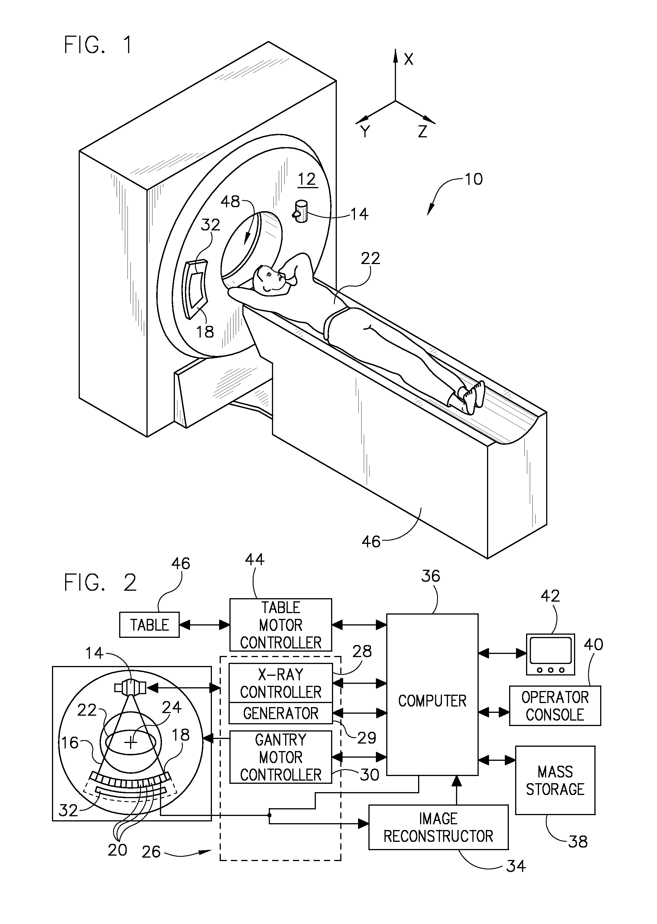
[0025]Diagnostics devices comprise x-ray systems, magnetic resonance (MR) systems, ultrasound systems, computed tomography (CT) systems, positron emission tomography (PET) systems, ultrasound, nuclear medicine, and other types of imaging systems. Applications of x-ray sources comprise imaging, medical, security, and industrial inspection applications. However, it will be appreciated by those skilled in the art that an implementation is applicable for use with single-slice or other multi-slice configurations. Moreover, an implementation is employable for the detection and conversion of x-rays. However, one skilled in the art will further appreciate that an implementation is employable for the detection and conversion of other high frequency electromagnetic energy. An implementation is employable with a “third generation” CT scanner and / or other CT systems.

[0026]The operating environment of the present invention is described with respect to a sixty-four-slice computed tomography (CT) ...


PUM


Abstract

A CT system includes a gantry, an x-ray source, a generator configured to energize the x-ray source to a first kVp and to a second kVp, a detector, and a controller. The controller is configured energize the x-ray source to the first kVp for a first time period, subsequently energize the x-ray source to the second kVp for a second time period, integrate data for a first integration period that includes a portion of a steady-state period of the x-ray source at the first kVp, integrate data for a second integration period that includes a portion of a steady-state period of the x-ray source at the second kVp, compare a signal-to-noise ratio (SNR) during the first integration period (SNRH) and the second integration period (SNRL), adjust an operating parameter of the CT system to optimize an SNRH with SNRL, and generate an image using the integrated data.

Description

BACKGROUND OF THE INVENTION[0001]The present invention relates generally to diagnostic imaging and, more particularly, to an apparatus and method of acquiring imaging data at more than one energy range using a multi-energy imaging source.[0002]Typically, in computed tomography (CT) imaging systems, an x-ray source emits a fan-shaped or cone-shaped beam toward a subject or object, such as a patient or a piece of luggage. Hereinafter, the terms “subject” and “object” shall include anything capable of being imaged. The beam, after being attenuated by the subject, impinges upon an array of radiation detectors. The intensity of the attenuated beam radiation received at the detector array is typically dependent upon the attenuation of the x-ray beam by the subject. Each detector element of the detector array produces a separate electrical signal indicative of the attenuated beam received by each detector element. The electrical signals are transmitted to a data processing system for analy...

Claims


Application Information

Patent Timeline
Patent Type & Authority Patents(United States)
IPC IPC(8): H05G1/60
CPCA61B6/032A61B6/405A61B6/482
Inventor LANGAN, DAVID ALLENTKACZYK, JOHN ERICLEBLANC, JAMES WALTERWILSON, COLIN R.WU, XIAOYEXU, DANBENSON, THOMAS MATTHEWPACK, JED DOUGLAS
Owner GENERAL ELECTRIC CO
Why Eureka
Try Eureka