Ultrasonic cerebral infarction therapeutic apparatus

a therapeutic apparatus and ultrasonic technology, applied in the field of ultrasonic cerebral infarction therapeutic apparatus, can solve the problems of high risk of promoting blood coagulation, low electroacoustic conversion efficiency of ultrasonic transducer attached to the point of a catheter, and limit the application of these methods to patients, so as to achieve no risk of causing a temperature rise in the brain tissu

Inactive Publication Date: 2010-11-09
FURUHATA HIROSHI +4
View PDF14 Cites 32 Cited by
  • Summary
  • Abstract
  • Description
  • Claims
  • Application Information

AI Technical Summary

Benefits of technology

[0020]Since this scheme prevents the ultrasonic wave beam irradiated into the cranium and its reflected beam from interfering with each other to produce an acoustic resonant state inside the cranium, and prevents the irradiated ultrasonic wave beam and the reflected beam from interfering with each other to produce a standing wave, risks of destruction of brain cells, occurrence of intracerebral hemorrhage, destruction of nerve tissue, etc. are eliminated.
[0021]Moreover, since the apparatus has a structure of suitably cooling the head and the ultrasonic transducers from the outside, there is also no risk of causing a temperature rise in the brain tissue.

Problems solved by technology

It is found that the catheter ultrasonic irradiation method described above causes the following inconveniences in the case of applying it to actual therapy.
However, such a large-sized image display is not widely spread, there is a limit in applying these methods to patients.
The second point is that the ultrasonic transducer attached on the point of a catheter has low electroacoustic conversion efficiency and is easy to generate heat, and therefore has a high risk of promoting blood coagulation.
However, it has become clear that the transcranial ultrasonic irradiation method produces following sixth and seventh points of inconveniences as will be described below.
The sixth point is that, although a low-frequency ultrasonic wave easily passes through the cranium, an ultrasonic beam irradiated into the cranium from the outside through one side thereof is reflected on the internal surface of the cranial bone on the other side, and the irradiated beam and the reflected beam interfere with each other to produce an acoustic resonant state inside the cranium, causing a temperature rise of the brain tissue.
The seventh point is that an ultrasonic beam irradiated into the inside of the cranium and a beam reflected on the internal surface of the cranial bone on the other side interfere with each other to produce a standing wave, and accordingly there is the possibility of generating an area where acoustic intensity increases abnormally at a spot inside the cranium, namely the so-called hot spot, which gives rise to risks of destruction of brain cells, occurrence of intracerebral hemorrhage, destruction of nerve tissue, etc.

Method used


Image

  • Ultrasonic cerebral infarction therapeutic apparatus
  • Ultrasonic cerebral infarction therapeutic apparatus
  • Ultrasonic cerebral infarction therapeutic apparatus

Examples


first embodiment

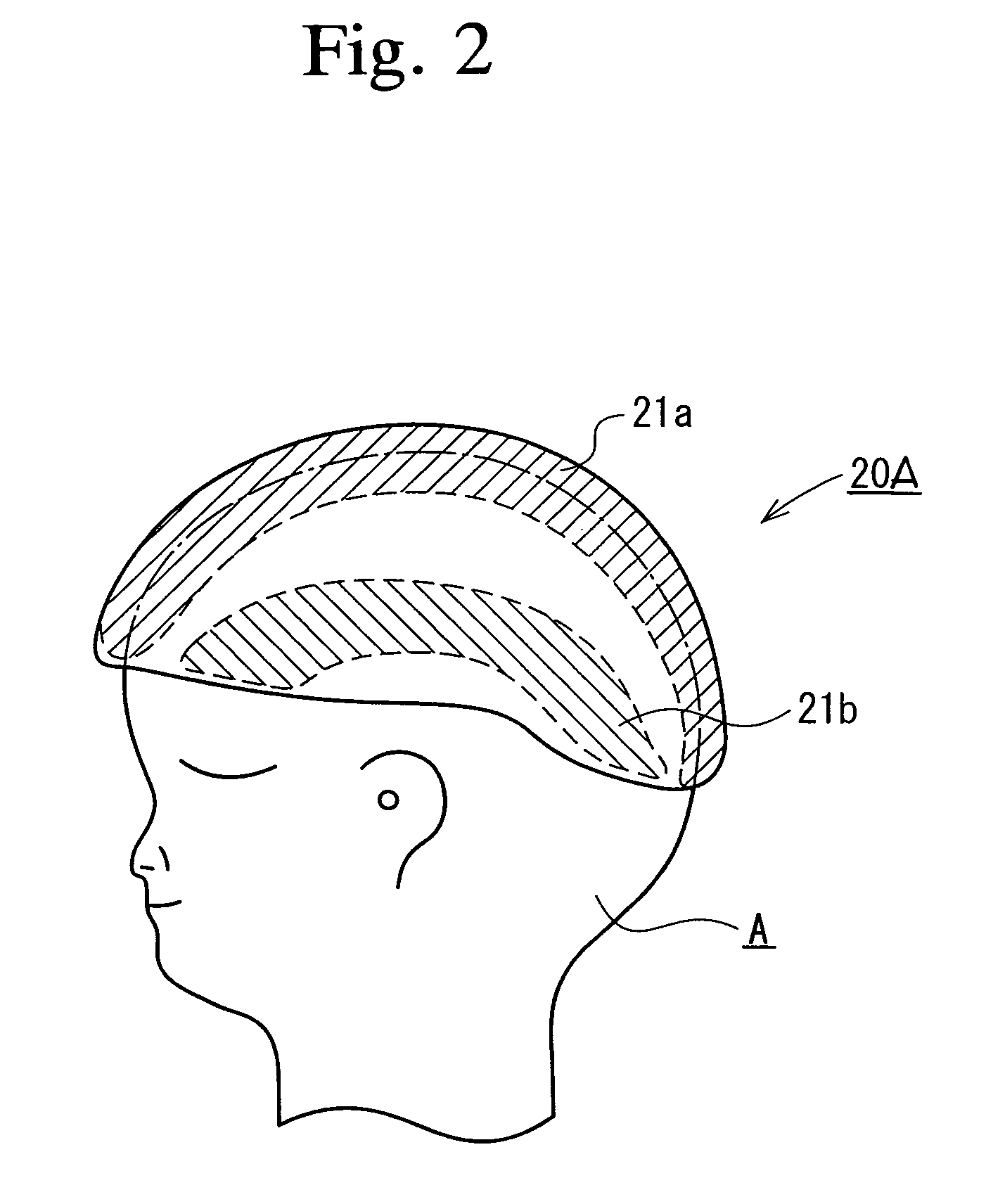
[0036]First, the ultrasonic probe cap 20A of the first embodiment will be explained. The ultrasonic probe cap 20A is a cap that is made up of a polyvinylidene fluoride (PVDF) film, as a row material, in the form capable of being brought into tight contact with the head and having flexibility. Although PVDF is a material that has an electromechanical transfer characteristic (piezoelectric characteristic), the efficient drive frequency is determined by the thickness of the film; therefore, in order to match the drive frequency with a comparatively low frequency being used in this embodiment, one that is made by laminating plural sheets of the films is desired.

[0037]However, in the case of a lamination of the films, it becomes difficult to bring it into tight contact with the head because of loss of the flexibility. Besides, it is necessary to configure the film so as to irradiate onto only the embolic site where thrombus occurred and so as not to irradiate the ultrasonic wave onto oth...

second embodiment

[0083]Next, the ultrasonic probe pad 20B that is the ultrasonic irradiation device 20 will be explained.

[0084]The ultrasonic probe pad 20B is a pad of the ultrasonic transducer having flexibility that is made up of a polyvinylidene fluoride (PVDF) film as a row material so that ultrasonic transducers can be attached to a part or the whole of the head of the patient under therapy A.

[0085]PVDF is a material having an electromechanical transfer characteristic (piezo-electric characteristic), and the thickness of its film determines an efficient drive frequency. Based on this fact, in order to match the ultrasonic probe pad 20B to a comparatively low frequency to be used, positive and negative electrodes are formed on the both sides of the PVDF film by means of vapor deposition etc. and necessary number of the films are laminated to constitute a pad of the ultrasonic transducer according to the drive frequency.

[0086]FIG. 10 is a diagram explaining the ultrasonic probe pad 20B of the sec...


PUM


Abstract

An ultrasonic cerebral infarction therapeutic apparatus that does not produce side effects of destruction of brain cells, occurrence of intracerebral hemorrhage, destruction of nerve cells, etc. by avoiding formation of a standing wave by interference between an irradiated beam of an ultrasonic wave irradiated to the inside of the cranium and its reflected beam. An ultrasonic probe cap is constructed by arranging a plurality of laminated small transducers each made up of a PVDF film, a PZT ceramic, or the like in a mosaic-like pattern or in other form on the inside of the cap and one or more transducers are selected and activated according to a thrombus position. As a high frequency for actuating a transducer, a continuous sinusoidal wave, a burst wave, or a pulse wave shall be used so that no standing wave may be produced inside the cranium.

Description

FIELD OF THE INVENTION[0001]This invention relates to an ultrasonic cerebral infarction therapeutic apparatus, and more specifically, to an ultrasonic cerebral infarction therapeutic apparatus that dissolves thrombus by irradiating an ultrasonic wave onto an embolic site of a cerebral infarction patient.BACKGROUND OF THE INVENTION[0002]For medical therapy of cerebral infarction (ischemic stroke), solving thrombus that caused cerebral infarction as early in the stage as possible after crisis is considered to be the most effective first selection. It is widely accepted that the sooner the restart of blood flow by dissolving the thrombus, the higher the effect of therapy becomes and the less the subsequent sequelae (dysphasia, paralysis, etc.) become.[0003]As thrombolytic agents, urokinase (UK), streptokinase (SK), tissue plasminogen activator (TPA) having high thrombus affinity, etc. are used to dissolve thrombus. It is considered effective to apply such a thrombolytic agent within th...

Claims


Application Information

Patent Timeline
Patent Type & Authority Patents(United States)
IPC IPC(8): A61H1/00A61B18/00A61N7/00
CPCA61N7/00A61B17/22004A61B2018/00011A61N2007/0078
Inventor FURUHATA, HIROSHIABE, TOSHIAKIMURAYAMA, YUICHISAGUCHI, TAKAYUKIISHIBASHI, TOSHIHIRO
Owner FURUHATA HIROSHI
Why Eureka
Try Eureka