Hermetic-type compressor

a compressor and hermetic technology, applied in the direction of positive displacement liquid engines, pumps, machines/engines, etc., can solve the problems of reducing reliability, affecting the smooth sliding movement, and reducing efficiency, so as to reduce the sliding loss, improve efficiency, and minimize the sliding area

Inactive Publication Date: 2010-11-16
PANASONIC CORP
View PDF19 Cites 7 Cited by
  • Summary
  • Abstract
  • Description
  • Claims
  • Application Information

AI Technical Summary

Benefits of technology

[0019]With this configuration, in the hermetic-type compressor of the present invention, thus comprised, even if the minute dust and refuses sucked up with the lubricant oil are collected in the vicinity of the lower end of the spiral groove and entered into the gap between the non-contact sliding-section of the main shaft and the main shaft bearing, the minute dust and refuses will be exhausted from the gap without stagnating there, because the gap at the non-contact sliding-section is large. Therefore, the hermetic-type compressor according to the present invention can realize an apparatus of a high efficiency and a high reliability, by preventing the lowering of efficiency by the increase of the input and the lowering of reliability by the damage and the abrasion in the sliding sections.
[0027]Moreover, the hermetic-type compressor according to the present invention may be structured to be driven by an inverter at a plurality of driving frequencies including those not greater than the commercial power source frequency. With the hermetic-type compressor of the present invention thus comprised, since reduction in the compressing load by the low driving frequencies can be realized, it is possible to lower the input to the hermetic-type compressor, and thus the power consumption of the refrigerating cycle in the refrigerator and the like can be greatly reduced.

Problems solved by technology

As a result, the input energy must be increased to obtain the desired output in the conventional hermetic-type compressor, thus inviting a decrease in the efficiency.
In addition, there is a problem that the reliability lowers due to the damage at the sliding sections 17.
Therefore, in the case of driving the conventional hermetic-type compressor at a low speed, the minute dust and small refuses further easily enter into a narrow gap between the sliding sections 17 and the main shaft bearing 16, thus damaging the smooth sliding movement.

Method used


Image

  • Hermetic-type compressor
  • Hermetic-type compressor
  • Hermetic-type compressor

Examples


first embodiment

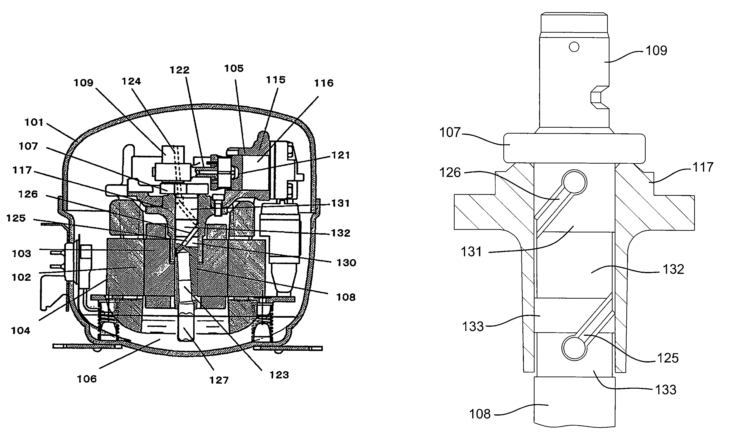
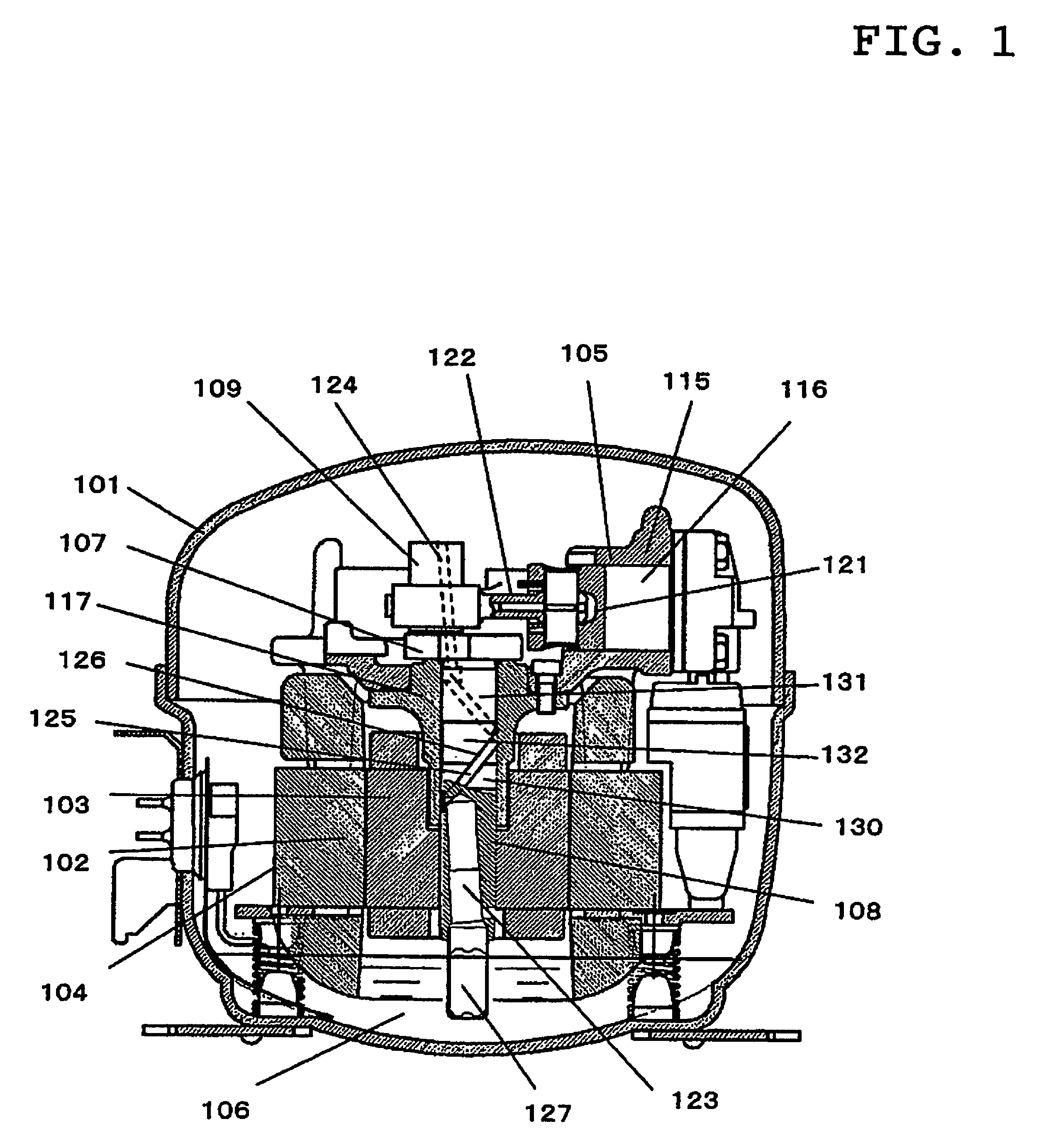
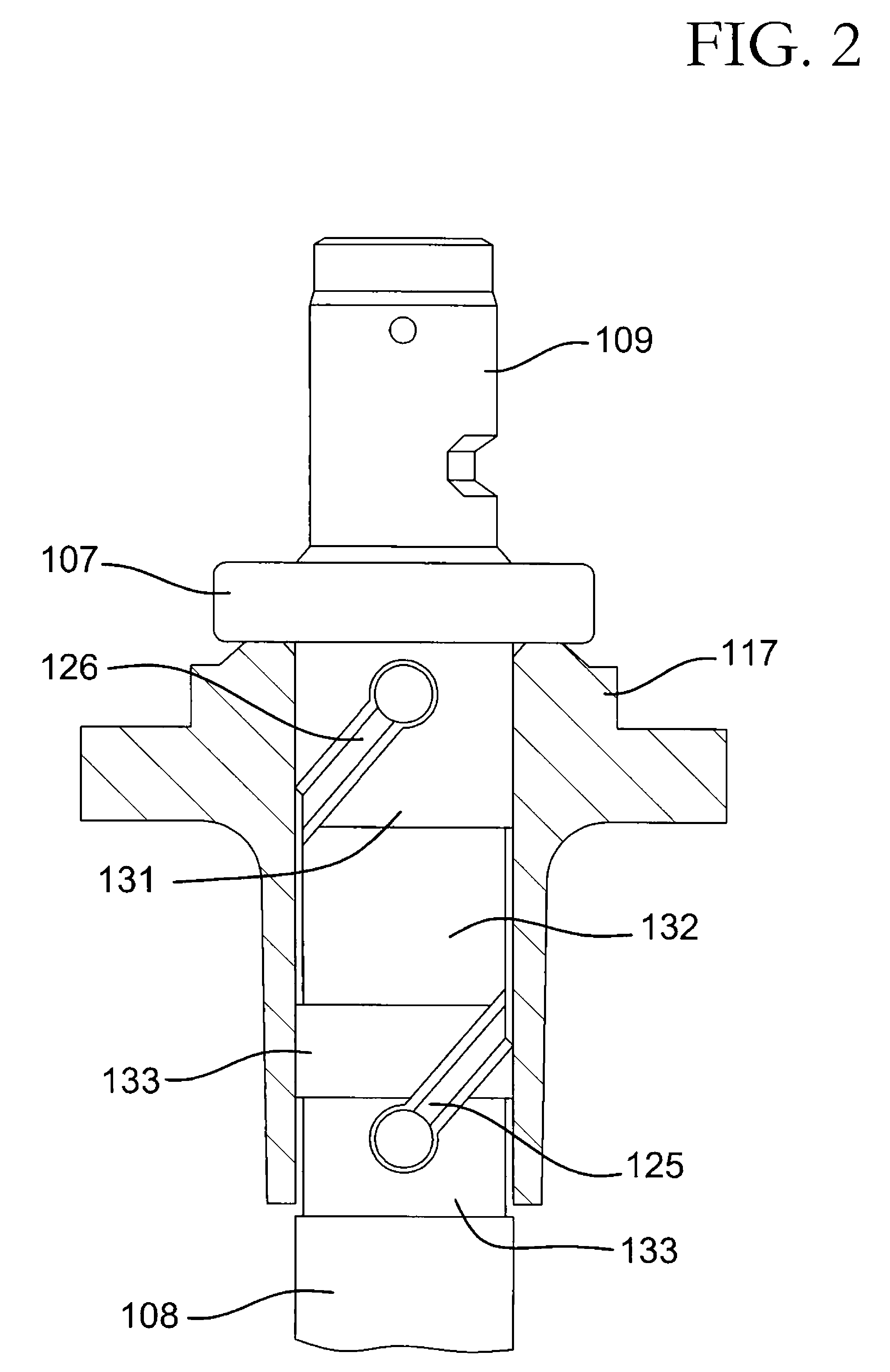
[0037]FIG. 1 is a longitudinal cross-sectional view illustrating an inner structure of a hermetic-type compressor of a first embodiment according to the present invention. FIG. 2 is a cross-sectional view showing the relevant part of the hermetic-type compressor of the first embodiment.

[0038]As shown in FIG. 1 and FIG. 2, an electric motor part 104 comprising a stator 102 and a rotor 103 and a compressor part 105 to be driven by this electric motor part 104 are provided in a hermetically sealed container 101. The hermetically sealed container 101 reserves lubricant oil 106 therein.

[0039]A crank shaft 107 which transmits the rotational driving force of the electric motor part 104 to the compressor part 105 comprises a main shaft 108, around which the rotor 103 is press-fit to be fixed, having an axis of rotation along a perpendicular line, and a crank part 109 being formed in an eccentric manner with respect to the center axis of rotation of the main shaft 108. A cylinder block 115 i...

second embodiment

[0059]A hermetic-type compressor according to a second embodiment of the present invention will be hereinafter described referring to FIG. 3 and FIG. 4 of the appended drawings. FIG. 3 is a longitudinal cross-sectional view illustrating an inner structure of the hermetic-type compressor of the second embodiment according to the present invention. FIG. 4 is a cross-sectional view showing a relevant part of the hermetic-type compressor of the second embodiment. In the second embodiment, parts and components having the same function and structure as those in the above-mentioned the first embodiment are denoted by the same reference numerals and the descriptions thereof are omitted. The different points in the structure of the hermetic-type compressor of the second embodiment from that in the hermetic-type compressor of the first embodiment are the structure of the crank shaft and the mechanism for rotatably supporting the crank shaft.

[0060]As shown in FIG. 3, the electric motor part 10...

third embodiment

[0075]A hermetic-type compressor according to a third embodiment of the present invention will be hereinafter described referring to FIG. 5 of the appended drawings. FIG. 5 is a cross-sectional view showing a relevant part of the hermetic-type compressor of the third embodiment. In the third embodiment, parts and components having the same function and structure as those in the above-mentioned the second embodiment are denoted by the same reference numerals and the descriptions thereof are omitted. The different point in the structure of the hermetic-type compressor of the third embodiment from those in the hermetic-type compressor of the second embodiment is the structure of the crank shaft. In the following description on the third embodiment, the points different from the second embodiment will be mainly described.

[0076]As shown in FIG. 5, a crank shaft 301 comprises a main shaft 302, a crank part 303 eccentrically formed with respect to the main shaft 302 and, an auxiliary shaft...


PUM


Abstract

A hermetic-type compressor according to the present invention has a viscous pump part by combining a spiral groove formed on the outer periphery of a main shaft with the inner periphery of a main shaft bearing, and at least one sliding section being in a sliding engagement with the main shaft bearing and at least one non-contact sliding-section having a predetermined gap with the main shaft bearing are formed on the face at the outer periphery of the main shaft opposing to the main shaft bearing where the lower end of the groove is located at the non-contact sliding-section.

Description

TECHNICAL FIELD[0001]The present invention relates to a hermetic-type compressor provided in a refrigerating cycle in such an apparatus as refrigerators, air conditioners and the like.BACKGROUND ART[0002]In recent years, for the hermetic-type compressor provided in the refrigerating cycle, to reduce the noise in the operation and to reduce the power consumption have strongly been desired on the assumption that the hermetic-type compressor should have high reliability. In order to meet such demand, some progresses have been made to lower rotational frequency of the compressor by driving it with an inverter and to lower viscosity for the lubricant oil to be used. In the case of performing a low-speed operation of such compressor using lubricant oil having low viscosity, it is an important task to supply the lubricant oil certainly to the sliding portions in the compressor. Namely, as such task for the recent hermetic-type compressors, it is an improvement in the reliability of the sli...

Claims


Application Information

Patent Timeline
Patent Type & Authority Patents(United States)
IPC IPC(8): F04B17/00F04B39/02F04B49/06F04B39/00
CPCF04B39/0253Y10S417/902F04B39/02F04B39/00
Inventor AKASHI, HIRONARITSUBOI, KOSUKE
Owner PANASONIC CORP
Why Eureka
Try Eureka