System and apparatus for cathodoluminescent lighting

a technology of cathodoluminescent lighting and system and apparatus, which is applied in the manufacture of electrode systems, electric discharge tubes/lamps, instruments, etc., can solve the problems of inefficiency of the process, low efficiency of the lighting system, and high cost of light-emitting diodes

Inactive Publication Date: 2010-11-16
VU1 CORP
View PDF26 Cites 18 Cited by
  • Summary
  • Abstract
  • Description
  • Claims
  • Application Information

AI Technical Summary

Problems solved by technology

This process, however, is generally inefficient because a significant amount of energy is lost to the environment in the form of extraneous heat and non-visible, infrared and ultraviolet, radiation.
While more efficient than incandescent lamps having tungsten filaments, fluorescent lamps tend not to have pleasing spectral characteristics, and light emitting diodes tend to be expensive.
Data display CRTs typically operate with deflection circuitry for steering their electron beams and have such tightly focused electron beams that operation without deflection may “burn” their phosphor coating causing permanent damage.
Triac dimmers typically work well with incandescent lighting and other resistive loads, reducing light intensity or heat output by reducing an on-phase of each AC cycle, but typically do not work well with electronic loads such as compact fluorescent lamps.
These current spikes cause these loads to have a poor “power factor”, and can cause inefficiencies in a power system.

Method used


Image

  • System and apparatus for cathodoluminescent lighting
  • System and apparatus for cathodoluminescent lighting
  • System and apparatus for cathodoluminescent lighting

Examples


embodiment 290

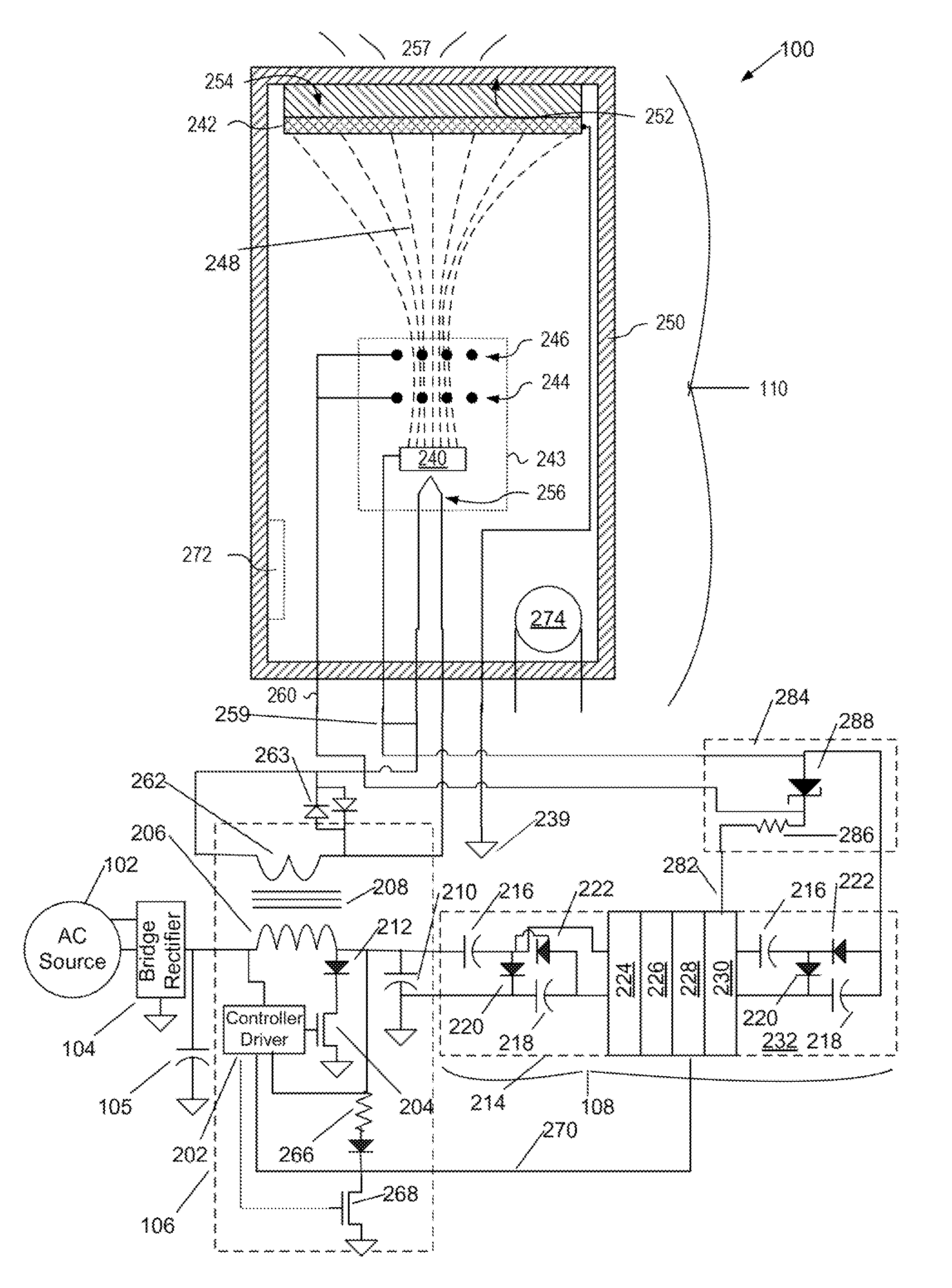
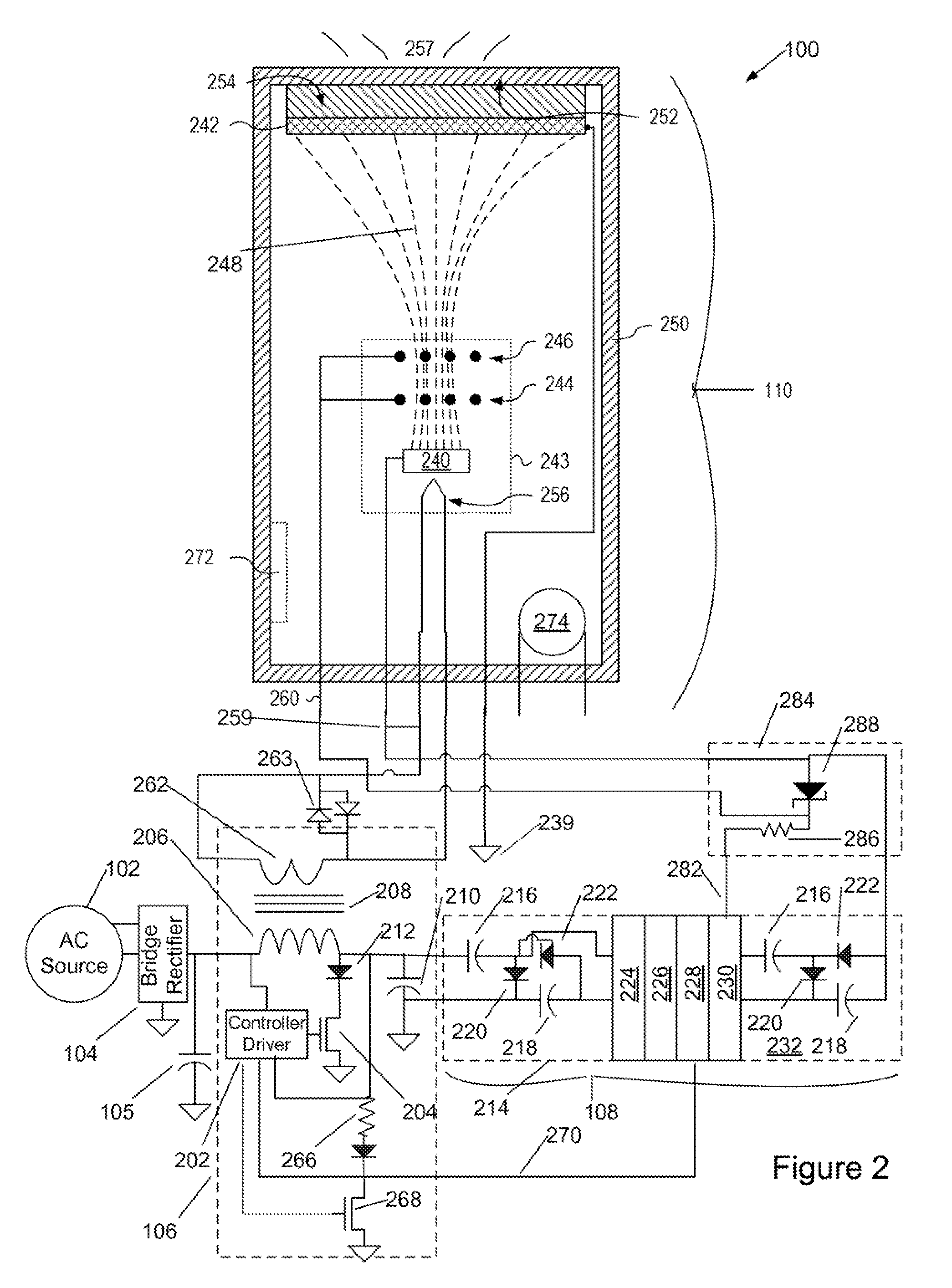
[0045]In the embodiment of FIG. 2, a voltage 282 between approximately one hundred and three hundred volts positive with respect to cathode 240 is tapped from the power supply formed by bridge rectifier 104, controller-inverter unit 106, and voltage multiplying rectifier 108; this voltage 282 is applied to the grid power and control 284 to provide a voltage 260 to extraction grid 244 and defocusing grid 246 of electron gun 243 of tube 110. In an embodiment, this supply incorporates a resistor 286 and Zener diode 288 to provide voltage 260 of approximately seventy-five volts positive with respect to the cathode 240; in alternative embodiments Zener diodes of other voltages may be used. In alternative embodiments, as illustrated in FIG. 2A, in an alternate embodiment 290 of the grid power and control 284, a small capacitor 291 taps an AC node in the voltage multiplying rectifier 108 to power a charge pump comprising diodes 292, 293, small filter capacitor 295 and Zener diode 294; the ...

embodiment 298

[0046]In yet another embodiments, as illustrated in FIG. 2B, in an alternate embodiment 298 of the grid power and control 284, a small inductor 298 is in series with capacitor 291 to tap an AC node in the voltage multiplying rectifier 108 to power a charge pump comprising diodes 292, 293, small filter capacitor 295 and Zener diode regulators 294. The extraction grid voltage may be derived from a modulator 296 or additional Zener diode. The charge pump is also coupled to the cathode 240 end of the voltage multiplier.

[0047]The power supply, including voltage-multiplying rectifier 108, grid power and control 284, and controller-inverter unit 106 is assembled using integrated circuit and surface-mount technologies as known in the art, and potted with a suitable high-voltage potting compound to prevent arcing.

[0048]In some embodiments, a voltage from a filter capacitor of the voltage-multiplying rectifier 108, which may be, but preferably is not, the highest output voltage of the voltage...


PUM


Abstract

A cathodolumineseent lighting system has a light emitting device having an envelope with a transparent face, a cathode for emitting electrons, an anode with a phosphor layer and a conductor layer. The phosphor layer emits light through the transparent face of the envelope. The system also has a power supply for providing at least five thousand volts of power to the light emitting device, and the electrons transiting from cathode to anode are essentially unfocused. Additional embodiments responsive to triac-type dimmers with intensity and color-changes in response to dimmer control. A power-factor-corrected embodiment is also disclosed.

Description

RELATED APPLICATIONS[0001]This application claims priority to U.S. Provisional Patent Application Ser. No. 60 / 888,187, filed Feb. 5, 2007, the disclosure of which is incorporated herein by reference. It is related to the material of copending, cofiled U.S. patent application Ser. No. 11 / 969,831, filed Jan. 4, 2008, entitled Cathodoluminescent Phosphor Lamp.FIELD OF THE INVENTION[0002]The present document describes a lighting device embodying a defocused cathode-ray device and driving circuitry. Embodiments have enhanced power factor and are compatible with conventional triac and other dimmers.BACKGROUND OF THE INVENTION[0003]Typically, lamps used for general lighting utilize a tungsten filament that is heated to generate light. This process, however, is generally inefficient because a significant amount of energy is lost to the environment in the form of extraneous heat and non-visible, infrared and ultraviolet, radiation. Other alternatives for general lighting include fluorescent ...

Claims


Application Information

Patent Timeline
Patent Type & Authority Patents(United States)
IPC IPC(8): H05B39/00H01J61/52
CPCH01J9/244H01J61/56H01J63/06
Inventor HUNT, CHARLES E.ZANE, REGAN ANDREWHERRING, RICHARD N.
Owner VU1 CORP
Why Eureka
Try Eureka