
Control algorithm using hysteresis sub-states in QAM modems

a control algorithm and sub-state technology, applied in the field of qam demodulators, can solve problems such as the decrease of qam modem latency, and achieve the effect of improving latency and reducing the latency of qam modem

Inactive Publication Date: 2010-11-16
REMEC BROADBAND WIRELESS NETWORKS LLC
View PDF5 Cites 5 Cited by
  • Summary
  • Abstract
  • Description
  • Claims
  • Application Information

AI Technical Summary

Benefits of technology

"The present invention provides a method and apparatus for automated acquisition of a QAM signal by using a control algorithm embedded in the QAM modem itself. This eliminates the need for physical access to the QAM modem and reduces latency. The control algorithm looks at the ultimate parameters to determine if the QAM modem is locked. The method includes performing automatic gain control, symbol timing recovery, Blind Equalization, carrier recovery, and decision directed equalization. The apparatus includes a state machine with various sub-states to perform these functions. The technical effects of this invention include improved latency, reduced latency, and improved automated acquisition of QAM signals."

Problems solved by technology

This results in decreased latency of the QAM modem.

Method used


Image

  • Control algorithm using hysteresis sub-states in QAM modems
  • Control algorithm using hysteresis sub-states in QAM modems
  • Control algorithm using hysteresis sub-states in QAM modems

Examples


Embodiment Construction

[0032]Reference will now be made in detail to the preferred embodiments of the invention, examples of which are illustrated in the accompanying drawings. While the invention will be described in conjunction with the preferred embodiments, it will be understood that they are not intended to limit the invention to these embodiments. On the contrary, the invention is intended to cover alternatives, modifications and equivalents that may be included within the spirit and scope of the invention as defined by the appended claims. Furthermore, in the following detailed description of the present invention, numerous specific details are set forth in order to provide a thorough understanding of the present invention. However, it will be obvious to one of ordinary skill in the art that the present invention may be practiced without these specific details. In other instances, well known methods, procedures, components, and circuits have not been described in detail as not to unnecessarily obsc...


PUM


Abstract

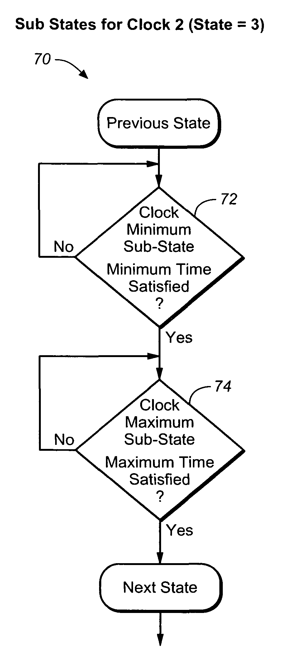
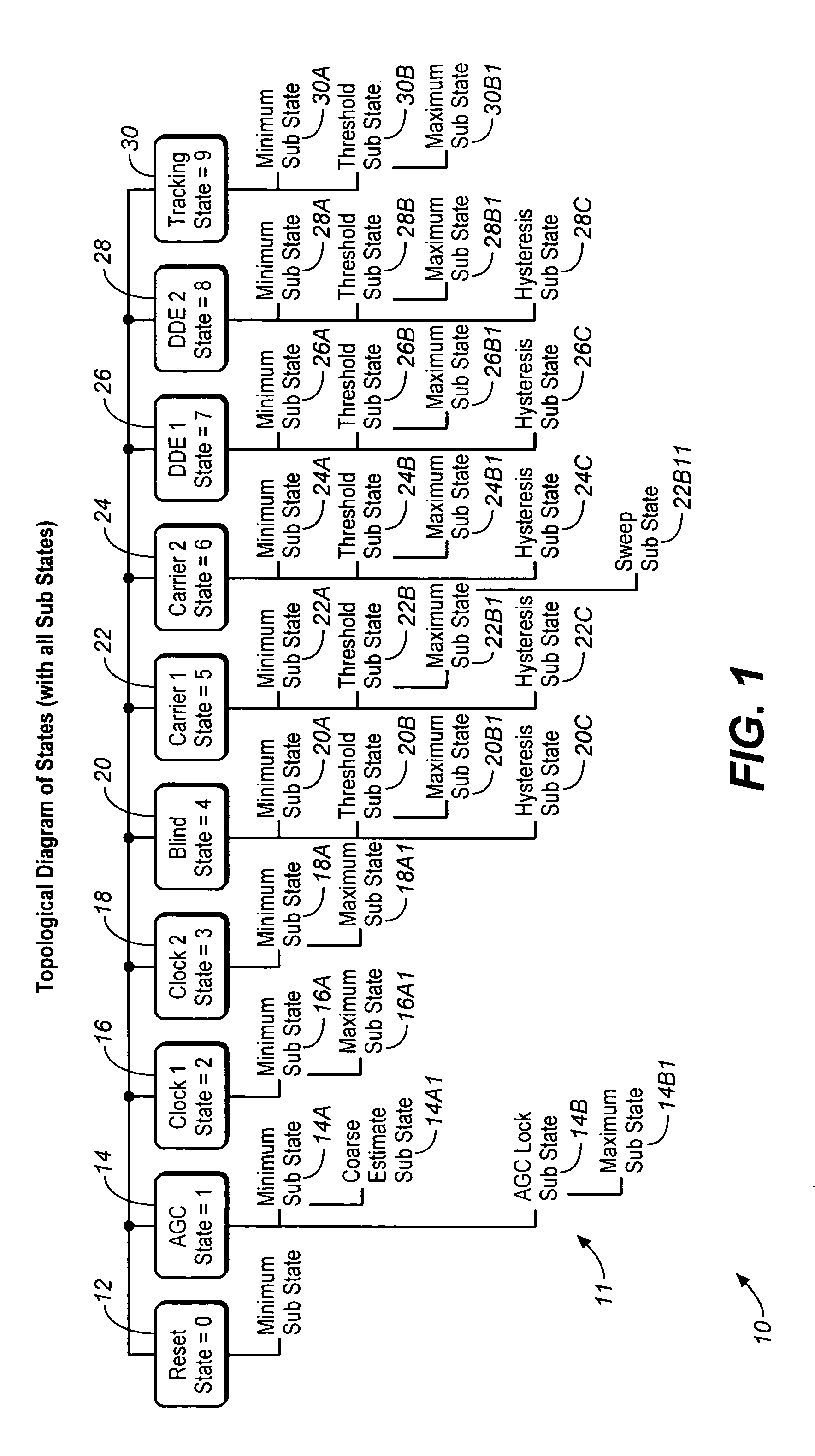
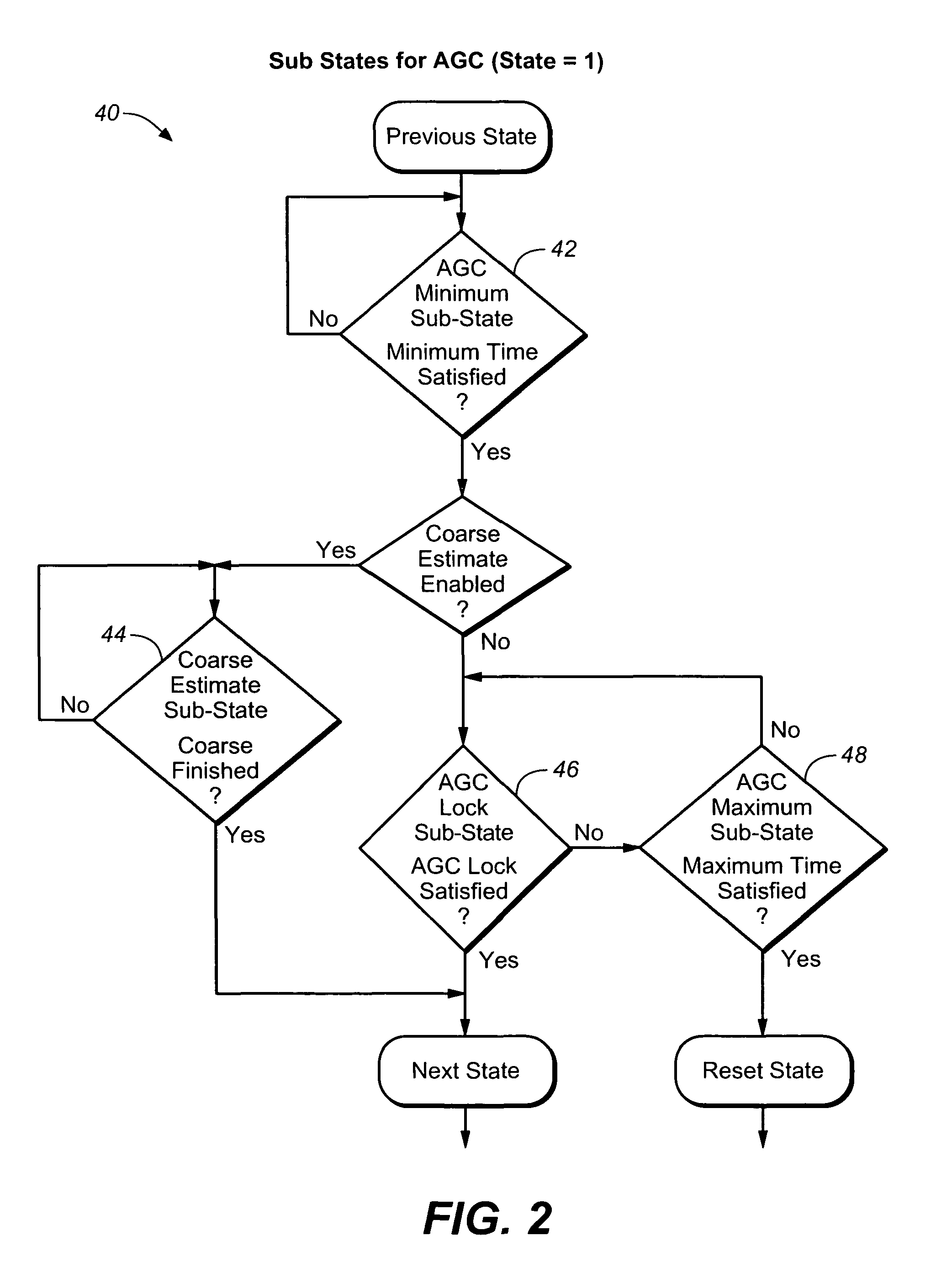
An apparatus for automated acquisition of a QAM signal. The apparatus employs a State machine progressing from an initial State to a final State. The State Machine comprises: (A) an AGC State further comprising a Minimum Sub-State further comprising: Coarse Estimate Sub-State; and an AGC Lock Sub-State further comprising Maximum Sub-State; (B) a Clock 1 State further comprising a Minimum Sub-State, and a Maximum Sub-State; (C) a Clock 2 State further comprising: a Minimum Sub-State; and a Maximum Sub-State; and (D) a Blind State further comprising a Minimum Sub-State; a Threshold Sub-State further comprising a Maximum Sub-State; and a Hysteresis Sub-State.

Description

[0001]This is a continuation-in-part of the U.S. patent application Ser. No. 10 / 734,415, “CONTROL ALGORITHM IN QAM MODEMS”, filed on Dec. 11, 2003 now abandoned.FIELD OF THE INVENTION[0002]The present invention is in the field of QAM demodulators. More specifically, the present invention relates to the field of control algorithms for QAM modems.DISCUSSION OF THE PRIOR ART[0003]Typically, in the prior art, an external Digital Signal Processor (DSP) is used to perform a controlling function for a QAM modem.[0004]However, in order to perform a controlling function for the QAM modem externally, the external DSP controller has to sequentially pull all relevant processing data associated with the QAM modem control function from the QAM modem itself. Thus, it is a Master-Slave model, in which the DSP external controller is a Master device, and the QAM modem is a Slave device. The drawback to this Master-Slave model to control the QAM modem is a high latency of such QAM modem control due to...

Claims


Application Information

Patent Timeline
Patent Type & Authority Patents(United States)
IPC IPC(8): H04J11/00
CPCH04L25/0305H04L27/3854H04L2027/0036
Inventor ISAKSEN, DAVID BRUCEFONG, MARK
Owner REMEC BROADBAND WIRELESS NETWORKS LLC
Learn More