Microphone array with physical beamforming using omnidirectional microphones

a microphone and beamforming technology, applied in the direction of frequency/directions obtaining arrangements, transducer types, electrical equipment, etc., can solve the problems of low frequency directivity loss, restricted inter-microphone spacing, and relatively modest directionality, so as to reduce the cost, the effect of expanding the working frequency range of the microphone array and reducing the cos

Active Publication Date: 2010-11-23
MITEL
View PDF23 Cites 38 Cited by
  • Summary
  • Abstract
  • Description
  • Claims
  • Application Information

AI Technical Summary

Benefits of technology

[0025]One advantage of the invention is the extension of the working frequency range for an existing narrow-band telephony microphone array to wide-band telephony (up to 7 kHz), without modifying the number of microphones. The invention effectively extends the working frequency range of a microphone array beyond its “limit” frequency, which depends on the inter-microphone distance. The invention operates at frequencies where beamforming is possible with only one or two microphones. Thus, the invention is operable with omnidirectional microphones, resulting in cost reduction and the ability to use inexpensive DSPs.
[0026]For medium frequencies (1.5 to 2 kHz), the combination of obstacle size and cavities provides high directivity with only one omnidirectional microphone. Alternatively, a wideband telephony conference unit may be provided where the number of microphones, the size and shape of the unit are optimised so that steering a high frequency beam from one sector to another is possible without digital beamforming, by simply selecting the microphone in the desired direction.

Problems solved by technology

The limitation of these systems is that they are either characterised by a fairly modest directionality or they are of costly construction.
The limitation of prior art microphone arrays is that the inter-microphone spacing is restricted to half of the shortest wavelength (highest frequency) of interest.
This means that for an increase in frequency range, the array must be made smaller (thereby losing low frequency directivity) or alternatively a microphones must be added to the array (thereby increasing cost).
Another problem with prior art microphone arrays is that the beamwidth decreases with increasing frequency and sidelobes become more problematic.
This results in significant off axis “coloration” of the signals.
As it is impossible to predict when a talker will speak, there is necessarily a period time during which the talker will be off axis with consequential “coloration” degraded performance.
However, the horn is bulky, can only be aimed in one direction and is therefore not very practical.
Another disadvantage is that the structure extends out from the surface of the device.
Moreover, all of the prior art systems discussed above use directional microphones that are more expensive than omni-directional microphones.

Method used


Image

  • Microphone array with physical beamforming using omnidirectional microphones
  • Microphone array with physical beamforming using omnidirectional microphones
  • Microphone array with physical beamforming using omnidirectional microphones

Examples


Embodiment Construction

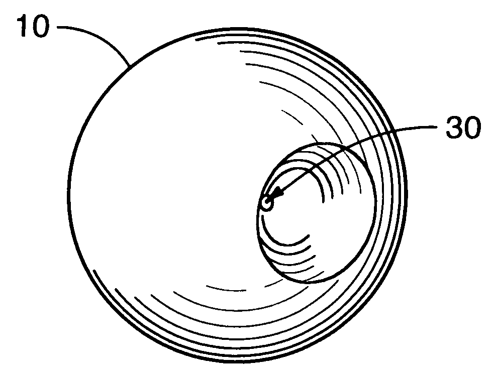
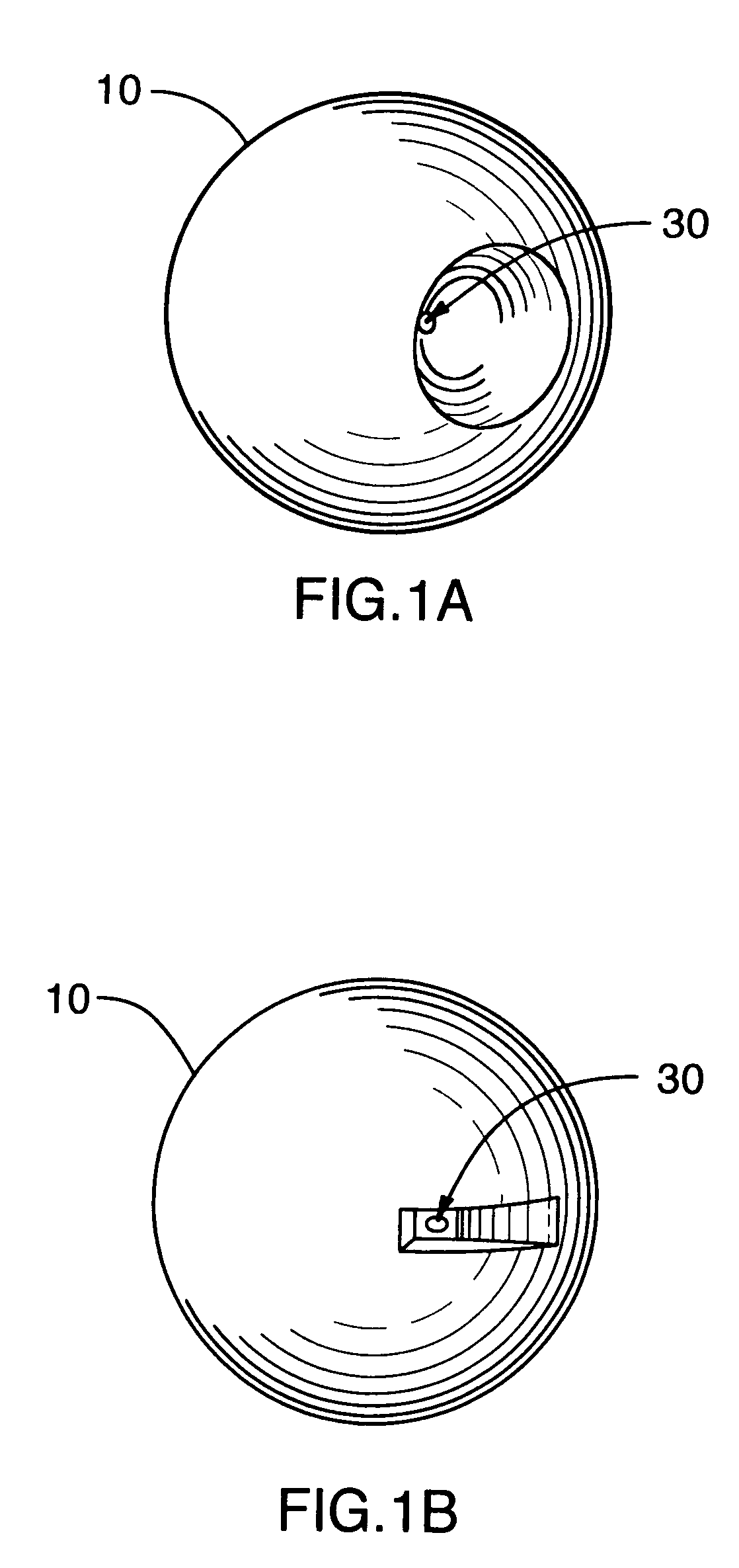
[0043]To illustrate the principles of the invention a conventional spherical shape of diffracting structure is first discussed for an array of embedded microphones. However, the concepts as applied to the simple sphere may be extended to more complicated shapes, as discussed in greater detail below with reference to FIG. 3 et seq.

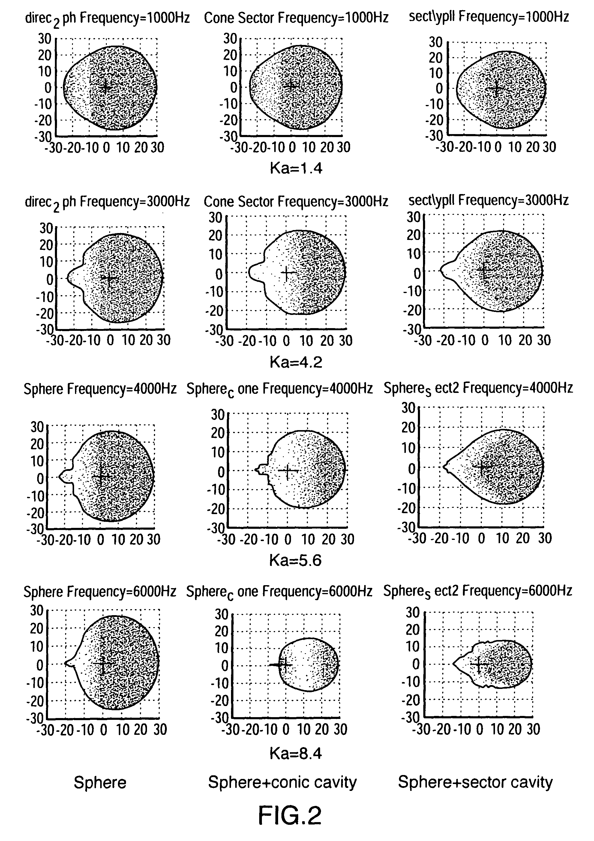
[0044]An analytical solution to the problem of a hard sphere is provided in Morse [9] (equation 7.2.18). An alternate solution is found in Meyer [4]. Considering the pressure field from a plane wave impinging upon the sphere from various directions, the pressure at a point on the sphere indicates the directionality. Naturally, the solution scales with the size of the object and the frequency. As illustrated in FIG. 2, no significant directionality occurs at frequencies below approximately ka<2 where k=2πf / c (f=frequency, c=speed of sound) and a is the radius of the sphere.

[0045]At lower frequencies (up to D=λ / 2 where D is the inter-element spacing) multiple...


PUM


Abstract

An array of microphones is provided wherein the microphones are positioned at the ends of cavities within a diffracting structure. The cavity depth, width, and shape are optimised to provide high directivity without grating lobes, at frequencies for which the distance between microphones is greater than half the acoustic wavelength.

Description

FIELD OF THE INVENTION[0001]The present invention relates in general to microphone arrays, and more particularly to a microphone array incorporating an obstacle having specific characteristics to improve the broadband sensor directivity and consequently the directivity of the array.BACKGROUND OF THE INVENTION[0002]Directional microphones are well known for use in speech systems to minimise the effects of ambient noise and reverberation. It is also known to use multiple microphones when there is more than one talker, where the microphones are either placed near to the source or more centrally as an array. Moreover, systems are also known for selecting which microphone or combination to use in high noise or reverberant environments. In teleconferencing applications, it is known to use arrays of directional microphones associated with an automatic mixer. The limitation of these systems is that they are either characterised by a fairly modest directionality or they are of costly constru...

Claims


Application Information

Patent Timeline
Patent Type & Authority Patents(United States)
IPC IPC(8): H04R3/00H04R1/40
CPCH04R1/406H04R2201/401
Inventor DEDIEU, STEPHANIEMOQUIN, PHILIPPE
Owner MITEL
Why Eureka
Try Eureka