Dynamic bandwidth allocation method with punishment mechanism in passive optical network

a bandwidth allocation and dynamic technology, applied in multiplex communication, digital computer details, instruments, etc., can solve the problems of increasing the average transmission delay of data, reducing the efficiency of bandwidth allocation, so as to achieve low transmission delay and high throughput

Inactive Publication Date: 2010-11-30
IND TECH RES INST
View PDF7 Cites 7 Cited by
  • Summary
  • Abstract
  • Description
  • Claims
  • Application Information

AI Technical Summary

Benefits of technology

[0014]It is a main object of the present invention to provide a dynamic bandwidth allocation method with punishment mechanism in PON, so as to effectively solve the problems of the prior art to achieve fair bandwidth allocation, low transmission delay and high throughput for the QoS data.
[0016]In comparison with the prior art, the present invention can directly guarantee QoS for data transmission by the upload / download bandwidth allocation method and punishment mechanism, accompanied by the queue transmission manner from high to low priority, so as to regulate the transmission delay of QoS, maintain the fairness of bandwidth allocation, and make the system vendor sign an agreement according to the requirements of the ONUs.

Problems solved by technology

Though Formulas (a) to (c) can effectively utilize the excess bandwidth, allocating excess bandwidth according to the proportion of the required bandwidth Ri of the ONUi does not satisfy the principle of fairness.
However, this method may increase the average transmission delay of data with other priorities, and the flow forecast error may reduce the utilization rate of the bandwidth.
The method can dynamically allocate bandwidth, but it may cause unfairness in that users have extremely large flow to occupy too much bandwidth.
Meanwhile, this method is not particularly applied to an EPON network.
However, the bandwidth of quality of service (QoS) cannot be definitely guaranteed.
One is unfairness, wherein if an ONU continues to ask for a great deal of bandwidth over a long time, the ONU may continue to occupy excess bandwidth, thus causing unfair bandwidth allocation.
The other is the delay problem, wherein during the network transmission, if a few ONUs continue to ask for a great deal of bandwidth over a long time, though the foregoing method can reduce their delay time, which majority of the other ONUs are prolonged, so the total delay time of the whole EPON is increased.

Method used


Image

  • Dynamic bandwidth allocation method with punishment mechanism in passive optical network
  • Dynamic bandwidth allocation method with punishment mechanism in passive optical network
  • Dynamic bandwidth allocation method with punishment mechanism in passive optical network

Examples


Embodiment Construction

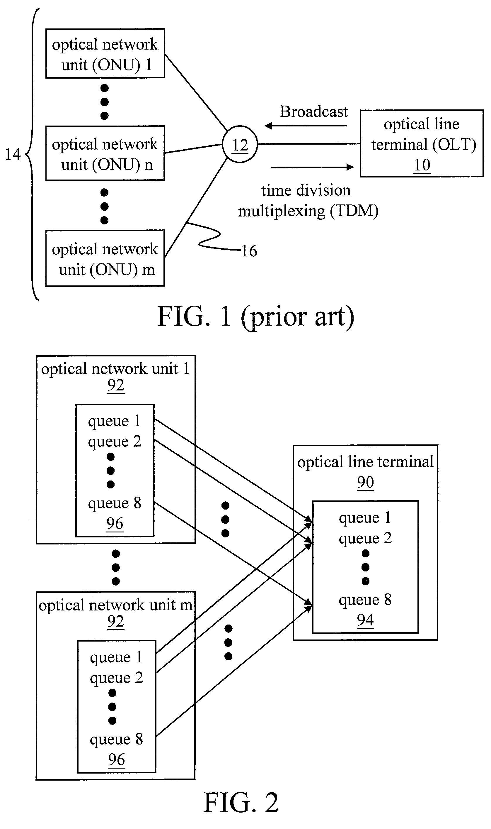
[0026]First, referring to FIG. 2, it is the architecture view of an OLT 90 and ONUs 92 with multiple queues according to the present invention. It can be seen from the drawing that, according to the present invention, the OLT 90 and the ONUs 92 are respectively provided with eight queues 94, 96. Dynamic bandwidth allocation is performed according to the priority and the uploaded data amount (bandwidth value) of each queue 96 at the ONUs 92, the downloaded data amount of each queue 94 at the OLT 90, and the punishment mechanism and bandwidth allocation principle of the present invention.

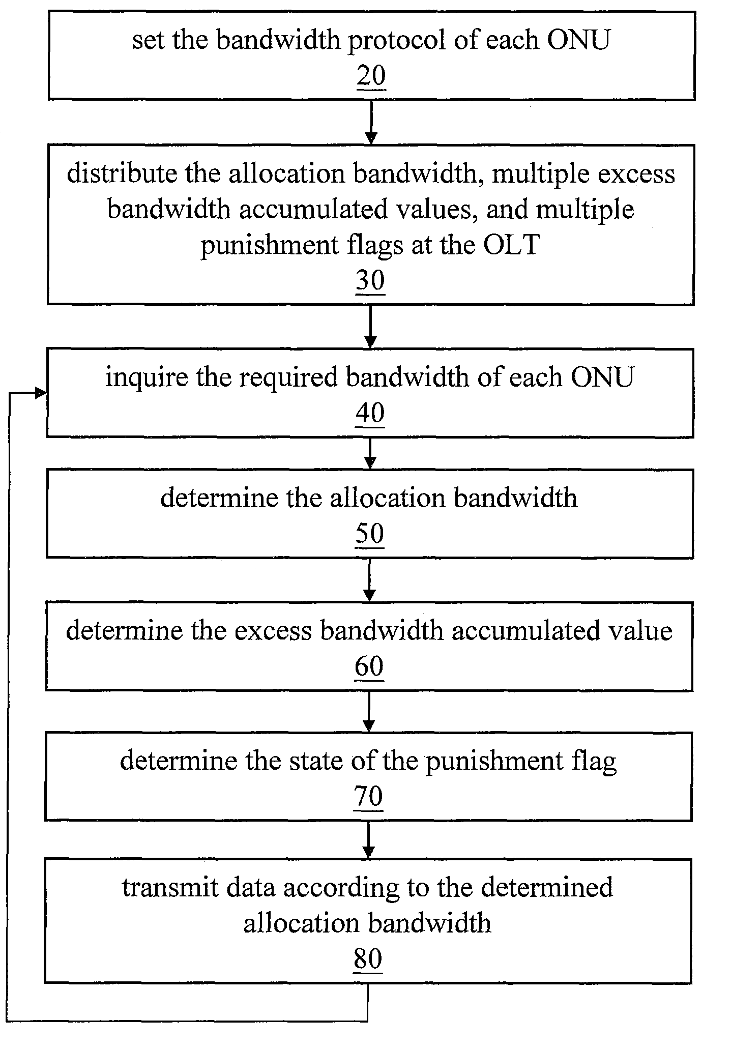
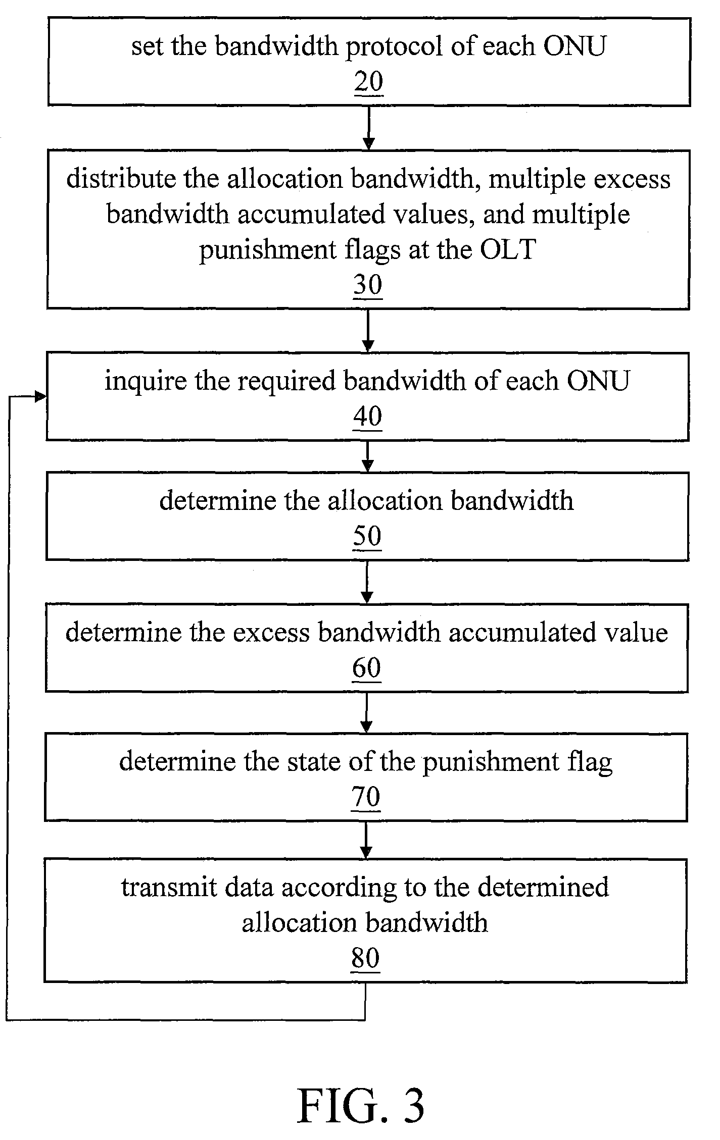
[0027]The dynamic bandwidth allocation of the present invention has two parts: data upload and data download. First, the bandwidth allocation method of data download is illustrated, which includes the following steps: (Step 1) summing all the downstream data amount of each queue 94 of the OLT 90, and calculating the required bandwidth; (Step 2) if the transmission period of the required bandwidth is l...


PUM


Abstract

A dynamic bandwidth allocation method with a punishment mechanism applicable in an Ethernet passive optical network (EPON) is provided. The method utilizes GATE message, report message format, and different data types of a multipoint control protocol (MPCP) to order various queues to make the queues have priority and transmit them sequentially in transmission. Meanwhile, the method can fairly allocate the bandwidth and reduce the delay time of queue according to an appropriately designed punishment mechanism and bandwidth allocation principle, so as to fulfill the requirements of Quality of Service (QoS).

Description

CROSS-REFERENCE TO RELATED APPLICATIONS[0001]This non-provisional application claims priority under 35 U.S.C. §119(a) on Patent Application No(s). 094146977 filed in Taiwan, R.O.C. on Dec. 28, 2005, the entire contents of which are hereby incorporated by reference.BACKGROUND OF THE INVENTION[0002]1. Field of Invention[0003]The present invention relates to a dynamic bandwidth allocation method in passive optical network (PON), and more particularly, to a dynamic bandwidth allocation method with a punishment mechanism, wherein the time allocation of each path during each cycle period is variable.[0004]2. Related Art[0005]Recently, PON has been increasingly utilized in research and industry. PON mainly includes Ethernet PON (EPON) and broadband PON (BPON) used in asynchronous transfer mode (ATM) network and so on. The main architecture of EPON is shown in FIG. 1, mainly constituting an optical line terminal (OLT) 10, a 1×N optical splitter 12, multiple optical network units (ONU) 14, a...

Claims


Application Information

Patent Timeline
Patent Type & Authority Patents(United States)
IPC IPC(8): H04J14/00
CPCH04J3/1694H04Q11/0001H04Q11/0067H04Q2011/0064
Inventor LAI, ZONE-CHANGKUO, HAN-CHUNGCHAO, SHANG-CHUNLIU, CHI-CHIENCHANG, CHIH-TANG
Owner IND TECH RES INST
Why Eureka
Try Eureka