Eureka AIR delivers breakthrough ideas for toughest innovation challenges, trusted by R&D personnel around the world.

Toroidal convection mixing device

a mixing device and convection technology, applied in the direction of machines/engines, biomass after-treatment, separation processes, etc., can solve the problem of not positioning the lowermost end of the air infusion tube, and achieve the effects of increasing the cell growth of microalgae, and increasing the density of the cultur

Inactive Publication Date: 2010-12-14
AGOIL INT
View PDF5 Cites 8 Cited by
  • Summary
  • Abstract
  • Description
  • Claims
  • Application Information

AI Technical Summary

Benefits of technology

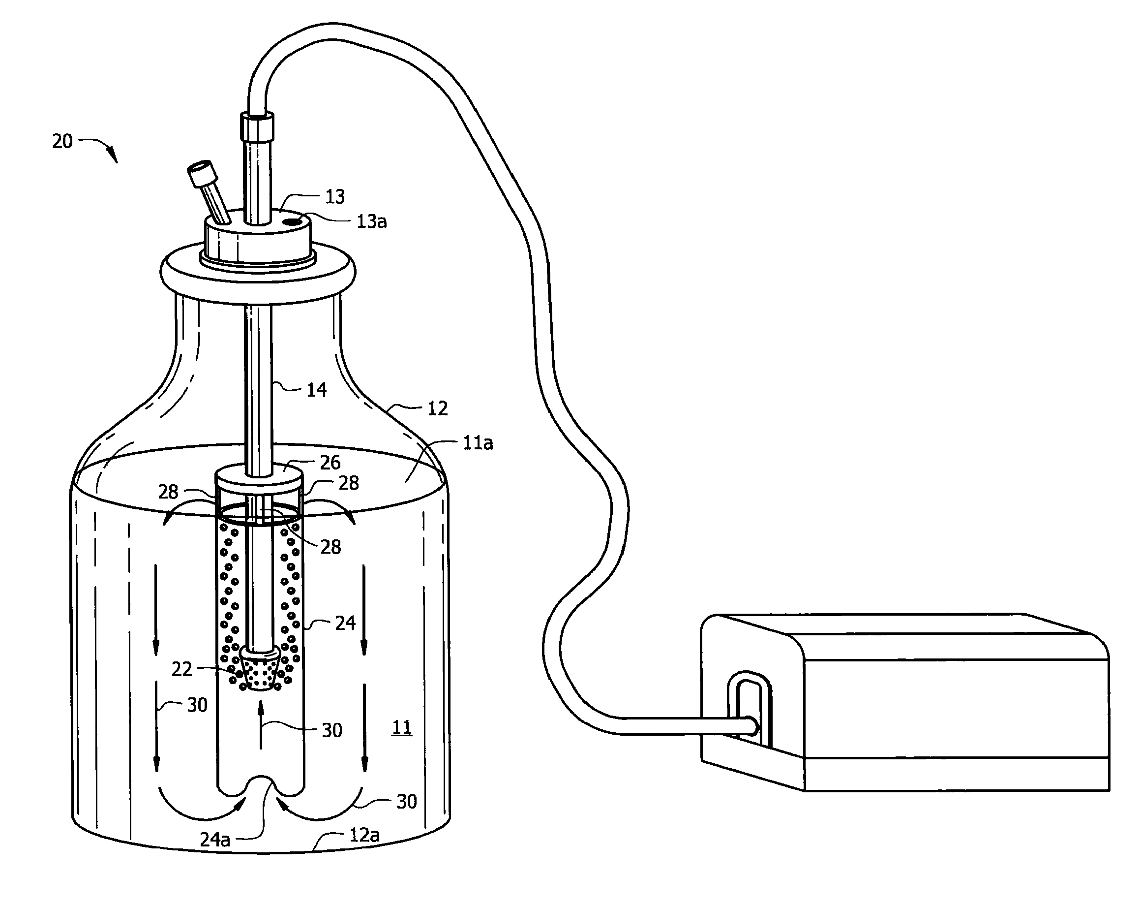
[0022]The diffuser is powered by a conventional aquarium-type pump. It continuously produces rising bubbles within the outer tube, thus creating an ongoing lifting motion of the liquid. The resulting action mixes the liquid thoroughly, but gently, circulates the contents vertically and radially in an even pattern, and infuses air and gases, all at the same time. The continuous circulation prevents settling of organisms and ingredients in the media. The uniformity of the media is continuously maintained throughout the vessel.
[0023]It is essential to provide equal access to illumination to all cells in a photosynthetic culture. It has been recognized for many decades that significant increase in cell growth of microalgae can be achieved by mixing cultures during growth so that cells can move in and out of high light intensity. Whereas only the outer ten percent (10%) of the culture volume would normally absorb the bulk of the illumination normally positioned in proximity to the vessel, the novel device enables the entire culture to receive uniform access to light by means of an efficient vertical and radial circulatory action. The rising bubbles from the diffuser at the bottom end of the inner tube work in tandem with the vacuum created at the bottom of the open-ended outer tube. The media is continuously lifted from the bottom of the vessel to the top and then circulated around the vessel. Continuous circulation that exposes all parts of the culture to the light source becomes even more critical as the density of the culture increases. The movement of the culture achieved by the novel device remedies the limitation of light penetration that routinely occurs when photosynthetic microbial cultures reach high density.
[0024]Uniform continuous mixing of the cultures is essential for aeration, circulation of CO2, nutrient distribution, and exposure to light. To consistently achieve high density culture, the novel device fulfills the mixing requirement, speeds growth, and boosts density in liquid cultures in an energy-efficient manner. The device increases the potential for higher cell concentrations, i.e., higher yield, in the same vessel without altering the media components or growth parameters.
[0025]The energy required to achieve thorough carboy mixing and gas infusion using the current invention is the same or less energy as has been consumed by prior art devices to achieve bubbling alone. This invention is an efficient and less expensive alternative to laboratory shakers, stirrers, reactors, or bubble columns.
[0026]A primary object of this invention is to provide an inexpensive, energy-efficient device that does a better job of mixing liquid culture media than conventional bubblers and mechanical shakers or stirrers.
[0027]Closely related objects include accomplishing the primary object while increasing the potential for higher yield cultures by providing enhanced aeration, circulation, CO2 circulation, nutrient distribution, and exposure to light.

Problems solved by technology

More particularly, the lowermost end of the air infusion tube is not positioned at the bottom of the vessel as in prior art bubbling devices.

Method used


Image

  • Toroidal convection mixing device
  • Toroidal convection mixing device
  • Toroidal convection mixing device

Examples


Embodiment Construction

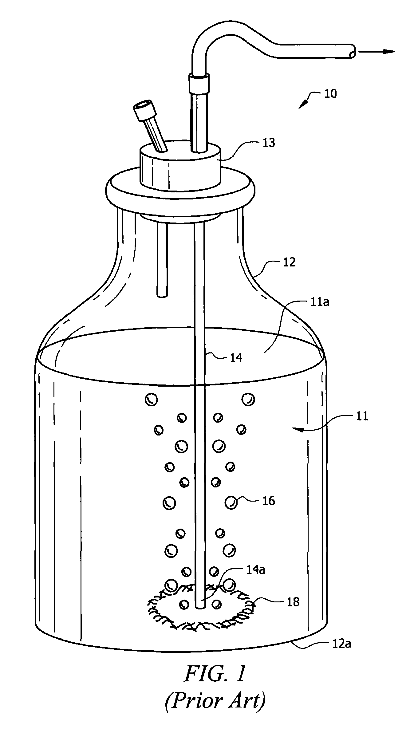
[0034]Referring first to prior art FIG. 1, it will there be seen that a prior art device is denoted as a whole by the reference numeral 10. Device 10 includes vessel 12 that preferably has a narrow neck so that it may be plugged with a stopper having plural bores formed in it. A first bore is needed to admit a tube into the vessel and a second bore is needed to provide a vent. Vessels having narrow necks that are closed with plugs having bores formed therein are of course well-known. A liquid culture media 11 having surface 11a is contained within vessel 12.

[0035]In FIG. 1, air infusion tube 14 has a trailing end in fluid communication with a pump, not shown, external to vessel 12. The bottom or leading end 14a of air infusion tube 14 is positioned in abutting relation to bottom wall 12a of vessel 12. When the remote pump is activated, bubbles 16 are created in liquid culture media 11 due to the very close proximity between leading end 14a of tube 14 and bottom wall 12a of vessel 12...


PUM

PropertyMeasurementUnit
diameteraaaaaaaaaa
timeaaaaaaaaaa
homogeneityaaaaaaaaaa

Abstract

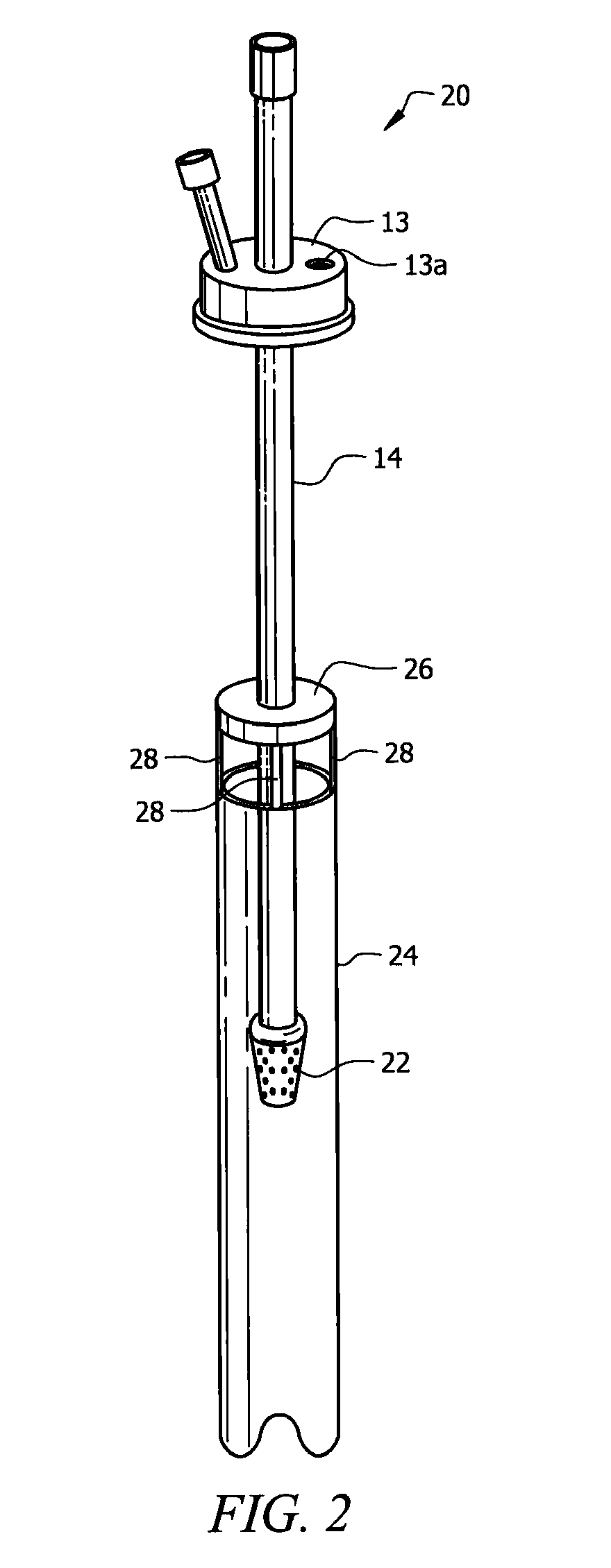
A device for circulating a liquid media in a vessel includes a gas infusion tube having a leading end immersed in the liquid media and a trailing end in fluid communication with a remote air pump. A diffuser is secured to the leading end of the gas infusion tube. The lumen of an outer tube receives the gas infusion tube and the diffuser. The outer tube has a leading end disposed in spaced relation to a bottom wall of the vessel and has a trailing end substantially flush with a level of the liquid media. A plurality of circumferentially spaced openings are formed in the trailing end of the outer tube or in a cap secured to the trailing end. Bubbles are emitted from the diffuser, entraining the liquid media so that it follows a toroidal path of travel that maximizes cell growth.

Description

BACKGROUND OF THE INVENTION[0001]1. Field of the Invention[0002]This invention relates to the mixing and gasification of a liquid in a vessel.[0003]2. Description of the Prior Art[0004]Liquid suspensions are conventionally prepared in microbial, chemical, and manufacturing applications by combining a variety of ingredients into narrow-necked vessels such as flasks or carboys. Mixing is required initially to distribute and dissolve the ingredients when preparing a suspension. After initial preparation, mixing is usually required on a continuous basis to maintain the suspension in a homogeneous state.[0005]Bacteria and algae are routinely grown in nutrient solutions in flasks or carboys in microbiological applications. The liquid media include a wide variety of ingredients. Aeration or gasification is often required for optimal growth of the culture. Continuous mixing of the liquid in the vessel is essential to ensure homogeneity of the media, circulation of nutrients, prevention of s...

Claims


Application Information

Patent Timeline
Patent Type & Authority Patents(United States)
IPC IPC(8): B01F13/02B01F33/40
CPCB01F3/04262B01F3/04517C12M27/20C12M29/06B01F2003/0429B01F2003/0439B01F23/231261B01F23/23123B01F23/232311
Inventor MUCH, ALAN MAXWELLMUCH, LEGAL REPRESENTATIVE, CAROLYN
Owner AGOIL INT
Why Eureka
Eureka Blog
Learn More