Method and apparatus for manufacturing high-purity alloy

a technology of high-purity alloy and manufacturing method, which is applied in lighting and heating apparatus, electric furnaces, furnaces, etc., can solve the problems of inability to accept phenomena, insufficient impurity content of higher-quality alloys, and too expensive methods so as to save the cost of physical vapor deposition or high-purity powder metallurgy , the effect of high-purity alloy

Active Publication Date: 2010-12-14
NAT CHUNG SHAN INST SCI & TECH
View PDF2 Cites 2 Cited by
  • Summary
  • Abstract
  • Description
  • Claims
  • Application Information

AI Technical Summary

Benefits of technology

[0005]An objective of the present invention is to provide a method and apparatus for manufacturing high-purity alloy that economize the cost of the method of physical vapor deposition or high purity powder metallurgy and high purity alloy is got.

Problems solved by technology

Furthermore, the impurity's content of the higher quality's traditional alloy must be limited.
However, this phenomenon is not accepted by the new materials of the solar cell, magnetic recording and semiconductor.
Nevertheless, the method of physical vapor deposition or high purity powder metallurgy is too expensive.
The method and apparatus for manufacturing high-purity alloy can economize the cost of the method of physical vapor deposition or high purity powder metallurgy.

Method used


Image

  • Method and apparatus for manufacturing high-purity alloy
  • Method and apparatus for manufacturing high-purity alloy
  • Method and apparatus for manufacturing high-purity alloy

Examples


Embodiment Construction

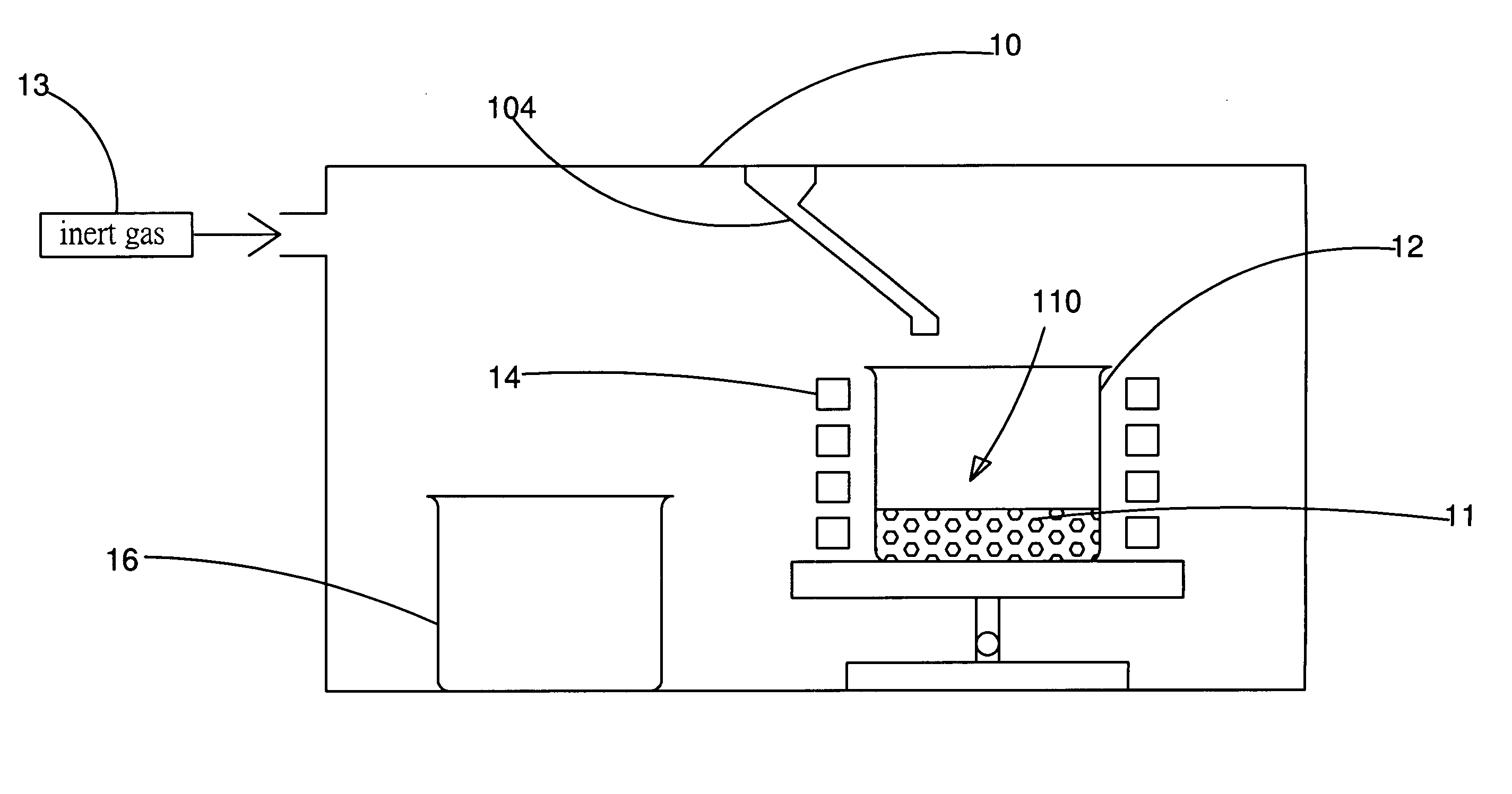
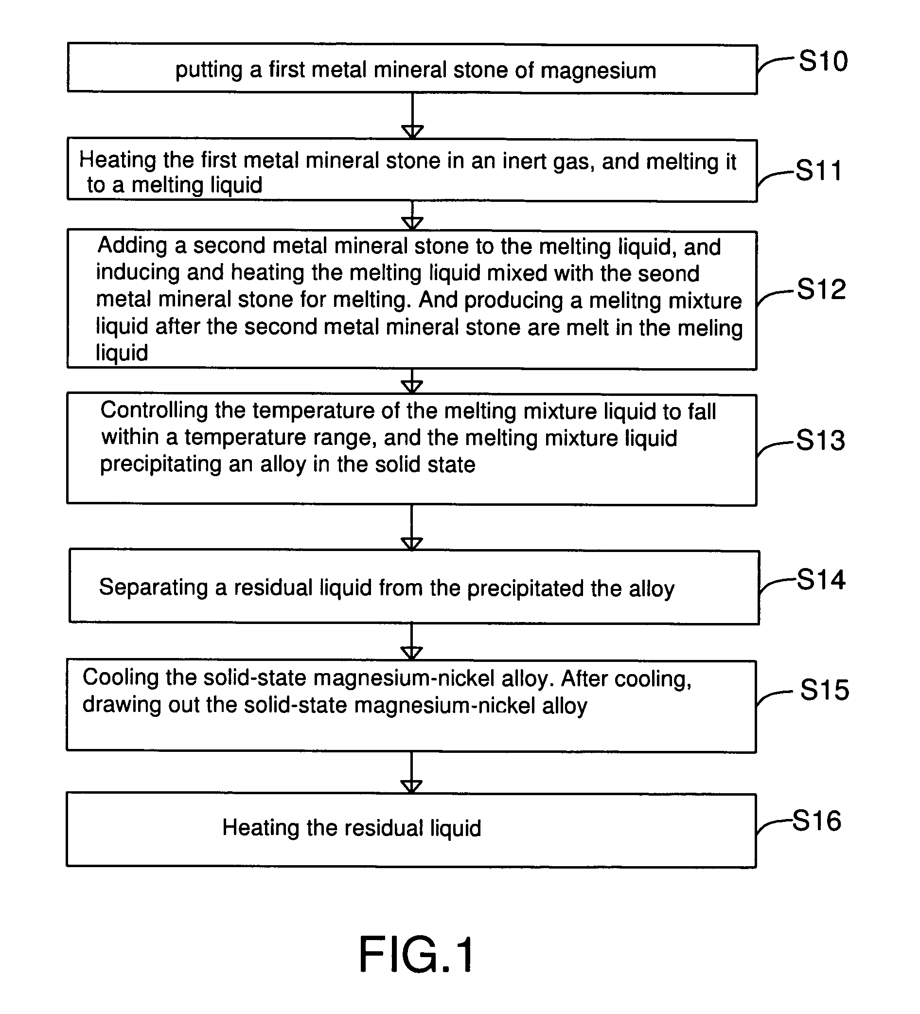
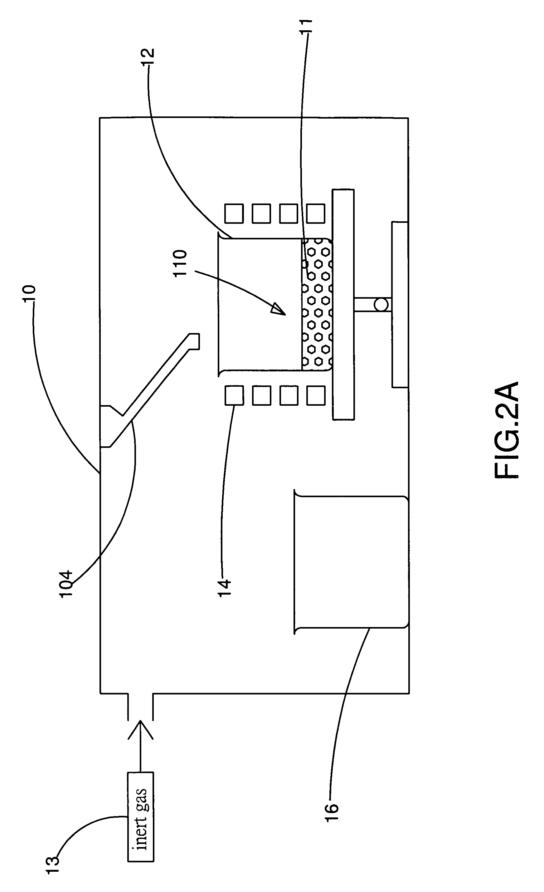
[0016]Refer to FIG. 1 and FIG. 2A show a flowchart and a schematic diagram of the apparatus in the steps S10 and S11 according to a preferred embodiment of the present invention. As shown in the figure, the present invention provides a method and apparatus for manufacturing high-purity alloy. The apparatus comprises a vacuum chamber 10 with a material feeding tube 104, a first crucible 12, an electromagnetic induction heat device 14 and a second crucible 16. By using the apparatus, the step S10 is executed for putting a first metal mineral stone 11 into the first crucible 12, where the first metal mineral stone 11 is a metal bulk, and the material of the first crucible 12 is a ceramic material with melting point greater than that of the feeding metal material. Then, gas an inert gas 13 into the vacuum chamber 10, and put the first crucible 12 with the first metal mineral stone 11 into the vacuum chamber 10. Before gassing the inert gas 13 into the vacuum chamber 10, the inert gas 13...


PUM

PropertyMeasurementUnit
purityaaaaaaaaaa
semiconductoraaaaaaaaaa
compositionaaaaaaaaaa

Abstract

An electromagnetic induction heat device to heat a first metal mineral stone and a second mineral stone to form a melting mixture liquid without stifling. The device keeps a temperature of the melting mixture liquid between solidus and liquidus of binary alloy phase diagram of the first and second metal mineral stone, then an alloy with solid state precipitates from said melting mixture liquid.

Description

FIELD OF THE INVENTION[0001]The present invention relates generally to a method and apparatus for manufacturing alloy, and particularly to a method and apparatus for manufacturing high-purity alloy.BACKGROUND OF THE INVENTION[0002]As the new products of the photo-electricity, semiconductor and energy are developed, the material's requirement is from the traditional alloy of steel or aluminum alloy to a new type's alloy, which is like the semiconductor's material of GaN, GaAs or CuInSe2. The composition of the traditional alloy has a specific range. Furthermore, the impurity's content of the higher quality's traditional alloy must be limited. Hence, the metallurgical technology or smelting method with tradition, for example, vacuum induction melting, utilizes online analysis to adjust each element of the composition in alloy melting's liquid state. Nevertheless, the precision of above online analysis's control just attains to ±0.1%. In cooling and solidify process, either much or lit...

Claims


Application Information

Patent Timeline
Patent Type & Authority Patents(United States)
IPC IPC(8): C22B9/04
CPCC22B9/003C22B9/02C22B26/22F27B14/061F27B14/0806C22B9/14C22B9/16Y02P10/20Y02P10/25
Inventor WU, YUAN-PANGBOR, HUI-YUNJENG, RONG-RUEY
Owner NAT CHUNG SHAN INST SCI & TECH
Why Eureka
Try Eureka