
Catalytic microcombustors for compact power or heat generation

Inactive Publication Date: 2011-01-04
DELAWARE UNIV OF A DE
View PDF40 Cites 18 Cited by
  • Summary
  • Abstract
  • Description
  • Claims
  • Application Information

AI Technical Summary

Benefits of technology

[0016]The present invention relates to techniques for producing electricity from hydrocarbons by coupling a thermoelectric element with a catalytic microcombustor. These systems currently exhibit efficiencies comparable to conventional batteries, but with virtually instant recharging (by simply adding more fuel) and negligible environmental impact. Due to the high energy density of hydrocarbons, these systems are also expected to eventually exhibit efficiencies significantly higher than traditional batteries. The micro reactors described herein could also be useful for synthesis of chemicals with improved yield and catalyst lifetime, inherent safety, and increased effective rates (process intensification).

Problems solved by technology

These systems currently exhibit efficiencies comparable to conventional batteries, but with virtually instant recharging (by simply adding more fuel) and negligible environmental impact.

Method used


Image

  • Catalytic microcombustors for compact power or heat generation
  • Catalytic microcombustors for compact power or heat generation
  • Catalytic microcombustors for compact power or heat generation

Examples


Embodiment Construction

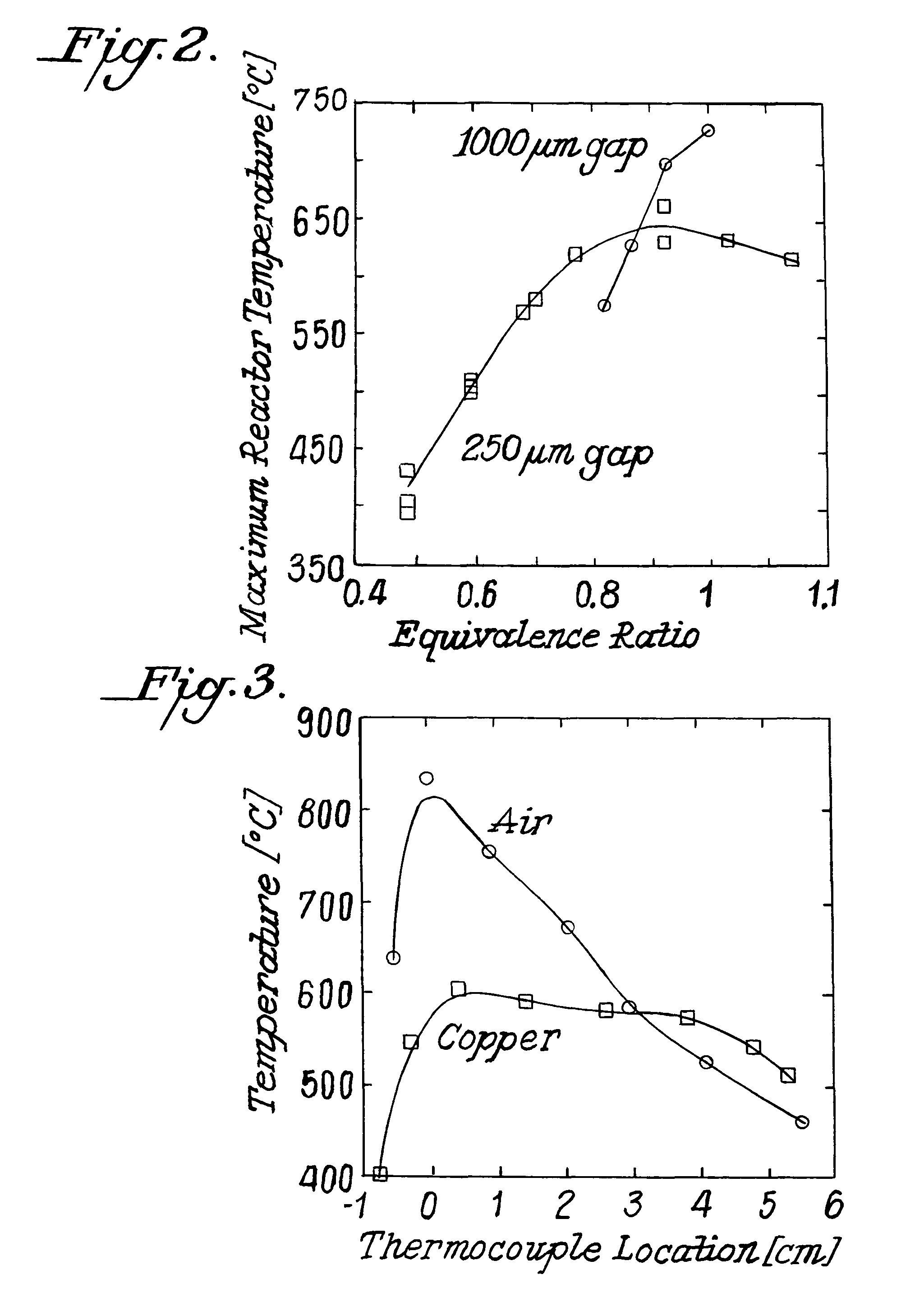
[0024]The present invention has numerous advantages over the prior art. For example, our system contains no moveable parts and exhibits low pressure drop. It has the maximum reported thermal efficiency in converting the energy of fuels into electricity. It uses regular fuels, such as hydrocarbons or hydrogen, to generate the heat needed on the hot side of the thermoelectric. The single channel catalytic microcombustor supports combustion in very shallow gaps, significantly below 1 mm, and achieves high transport rates and complete conversion of the fuel. It controls the temperature uniformity by suitable material design and selection at the hot side of the thermoelectric to increase efficiency. It allows control of the maximum temperature exposed to the hot side of the thermoelectric to avoid damage of the thermoelectric element. It exhibits no detectable emissions of hydrocarbons or carbon monoxide. It allows control of temperature profiles for improved catalyst life time and perfo...


PUM


Abstract

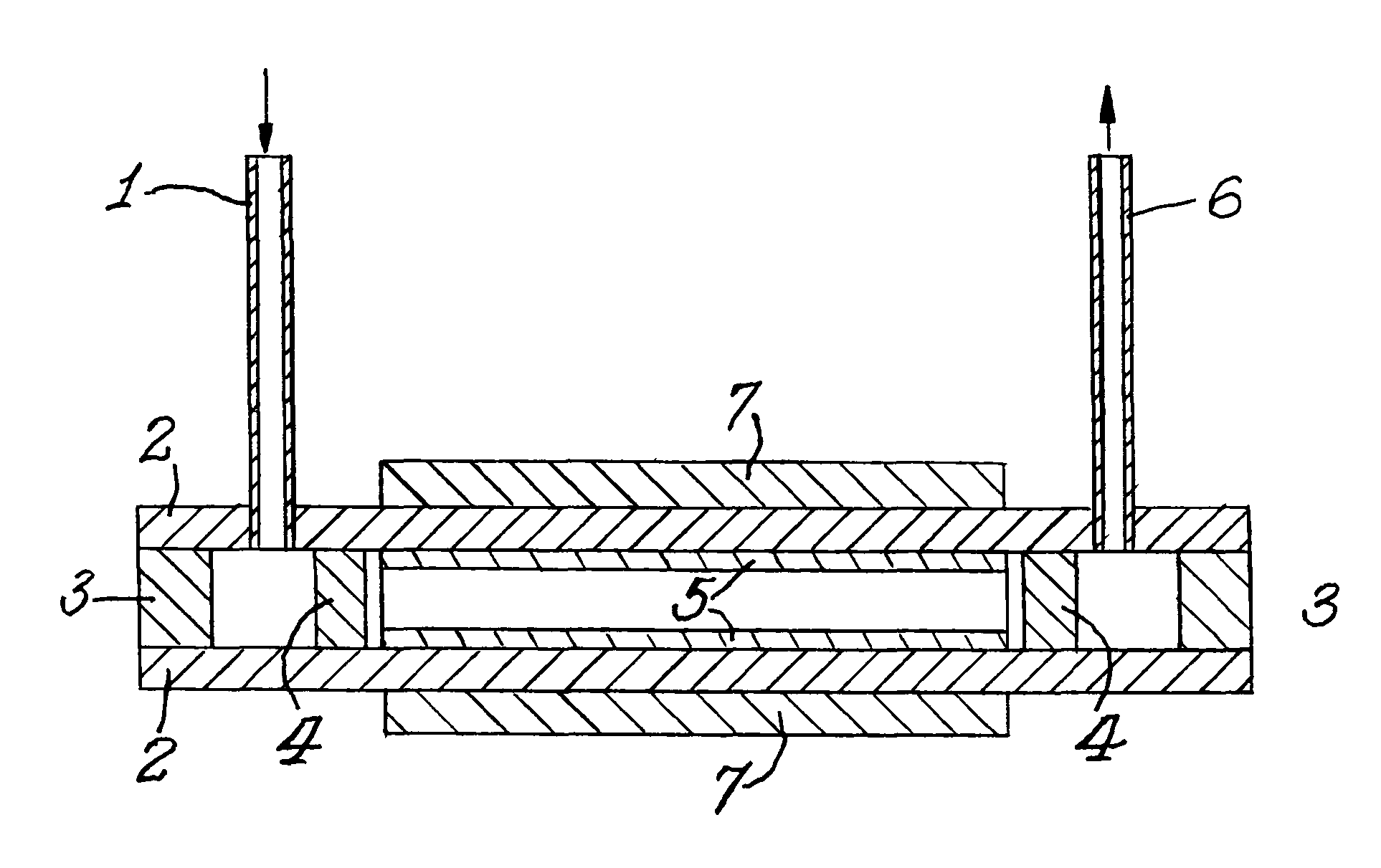
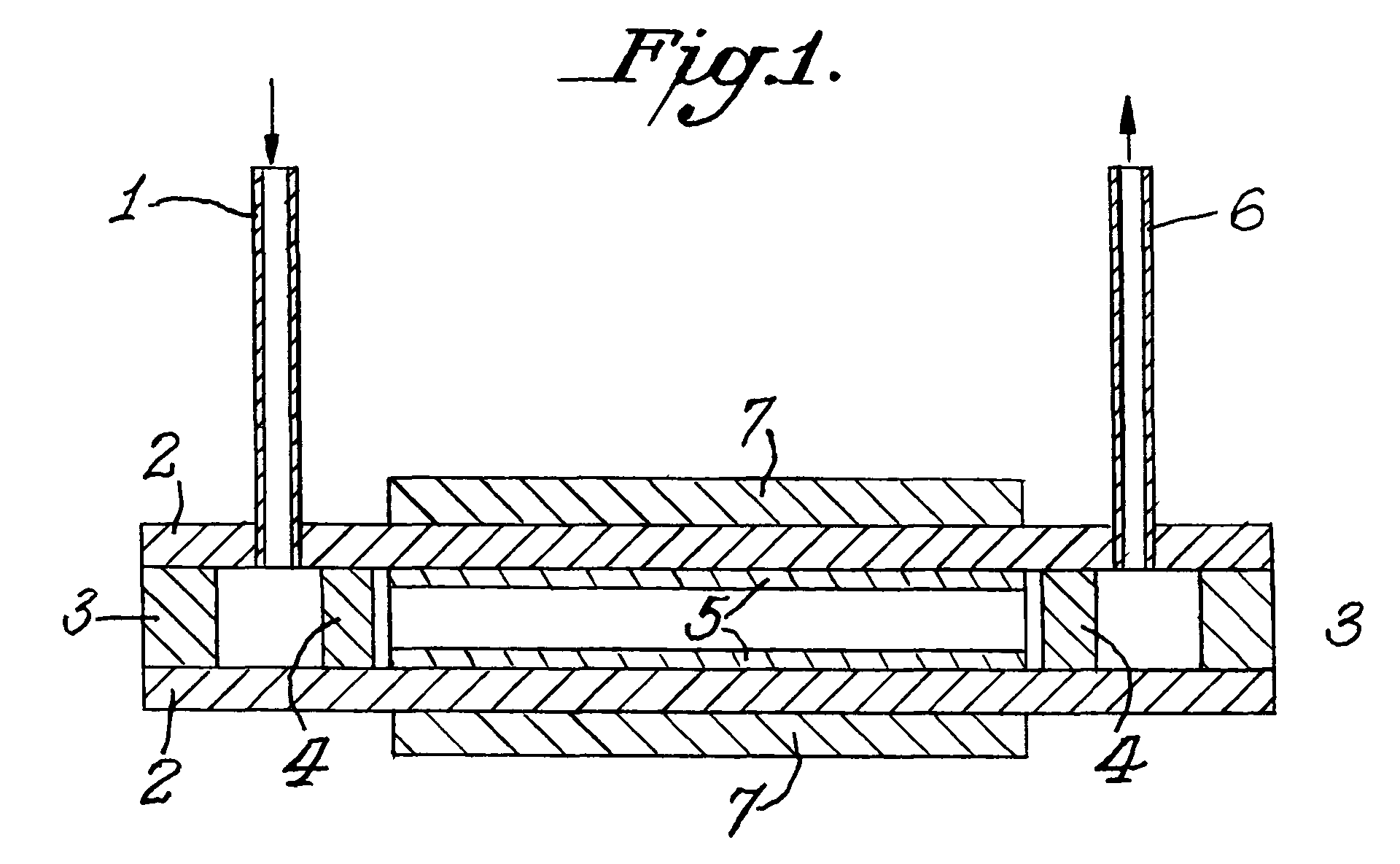
The present invention comprises a device which utilizes catalytic microcombustion for the production of heat or power and which exhibits a low pressure drop and has a high catalytic surface area. The catalytic microcombustor includes catalyst inserts in the reaction chamber separated by a sub millimeter distance. Thermal spreaders ensure temperature uniformity and maximum thermal efficiency. A mixing zone is prior to the combustion zone. Thermally conductive and / or insulating inserts are in the vicinity of the reaction zone.

Description

CROSS-REFERENCE TO RELATED APPLICATION[0001]This application is based on provisional application Ser. No. 60 / 691,990, filed Jun. 17, 2005.GOVERNMENT LICENSE RIGHTS[0002]The United States Government has rights in this invention which was done under CMR funding which is a program of the Center of Composite Materials funded by the Army Research Laboratory.BACKGROUND OF INVENTION[0003]A number of consumer, commercial and military applications require improved power sources for portable electronic equipment. Traditional batteries suffer from a number of limitations. In most applications, batteries are either too heavy or do not last long enough. Recharging times for reusable batteries are very slow (typically hours), and in fact the highest energy density batteries are single-use. Most battery chemistries also use heavy metals and other toxic materials, which present safety and health risk, as well as environmental disposal complications.[0004]Electricity needed for portable electronic d...

Claims


Application Information

Patent Timeline
Patent Type & Authority Patents(United States)
IPC IPC(8): F23Q11/00F23D3/40
CPCF23C13/02F23C13/08H01L35/30H01M8/0606H01M14/00H01M16/003F23C2900/03001H01M2250/407Y02T10/166Y02E60/50Y02E60/563Y02T10/12H10N10/13
Inventor NORTON, DANIEL G.WETZEL, ERIC DEANVLACHOS, DIONISIOS G.
Owner DELAWARE UNIV OF A DE
Learn More