
Method and apparatus for driving capacitive load, and LCD

a capacitive load and capacitive load technology, applied in the field of methods and apparatus for driving capacitive load and lcd, can solve the problems of inability to control the power supply circuit, the power supply circuit is always occupied by current i, and the display quality of the cell is affected, so as to reduce the power consumption rate, suppress the variation of driving potential, and reduce the charge and discharge current

Inactive Publication Date: 2011-01-04
ROHM CO LTD
View PDF8 Cites 1 Cited by
  • Summary
  • Abstract
  • Description
  • Claims
  • Application Information

AI Technical Summary

Benefits of technology

[0014]In order to solve the problems described above, preferred embodiments of the present invention provide a method and a drive unit that enables driving capacitive loads without increasing the size of the drive unit, with reduced charging and discharge currents and with suppressed variations in the driving potential supplied to the capacitive loads, and hence at a reduced power consumption rate. Another preferred embodiment of the present invention provides an LCD equipped with such a drive unit.
[0032]Preferred embodiments of the present invention can reduce the size of a capacitive load drive unit. Nevertheless, the present invention can reduce charging and discharging currents through capacitive loads, and hence the power consumption involved, and variations in the driving potential supplied to the loads as well.
[0033]It should be appreciated that the variations in the driving potential of liquid crystal cells of an LCD can be reduced while suppressing the degradation of display quality of an LCD.

Problems solved by technology

Such potential drop disadvantageously causes an adverse influence on the liquid crystal cell (e.g. degradation of display quality of the cell).
In addition, since the current I is supplied from the first and second power supply circuits 10 and 20, respectively, inevitable power consumption of the current I takes place in these power supply circuits.
However, this prior art requires a charge storage capacitor of large capacitance which cannot be easily embedded in an IC chip together with a relevant power source circuit and switching circuits, so that the capacitor must be separately provided as a discrete component, thereby makes the drive disadvantageously large in size.
Another problem arises in the use of such a charge storage capacitor as mentioned above that it requires dummy periods in addition to the scanning periods, which in turn requires controlling the driving potential supplied to the signal electrodes during the dummy periods.

Method used


Image

  • Method and apparatus for driving capacitive load, and LCD
  • Method and apparatus for driving capacitive load, and LCD
  • Method and apparatus for driving capacitive load, and LCD

Examples


Embodiment Construction

"d_n">[0040]FIGS. 6(a)-6(c) illustrate typical behaviors of driving potentials Vs in a conventional, an ideal, and a non-ideal driving schemes.

[0041]FIG. 7 illustrates a principle for reduction of consumption current.

[0042]FIG. 8 shows an exemplary arrangement of a signal electrode driver 2.

[0043]FIGS. 9(a)-9(c) show equivalent circuit of the segments undergoing simultaneous transitions from a first potential V1 to a third potential Vm.

[0044]FIG. 10 is a timing diagram of PWM control of the load driving periods for neighboring segments.

[0045]FIG. 11 is an equivalent circuit of the segments undergoing simultaneous changes from a first potential V1 to a third potential Vm and from a second potential V2 to the third potential Vm.

[0046]FIG. 12 shows an arrangement of a conventional capacitive load drive unit for driving a capacitive load.

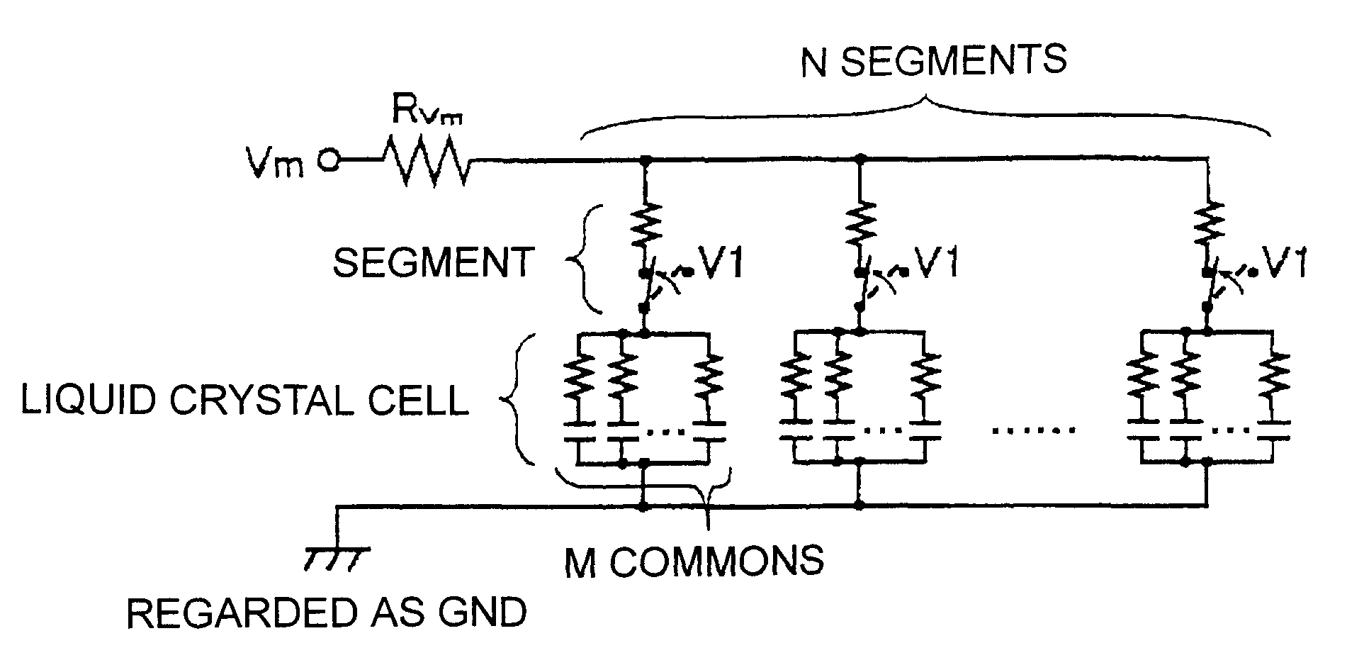
[0047]FIG. 13 is a timing diagram of the drive unit shown in FIG. 12.

DETAILED DESCRIPTION OF PREFERRED EMBODIMENTS

[0048]A method and a drive unit accor...


PUM


Abstract

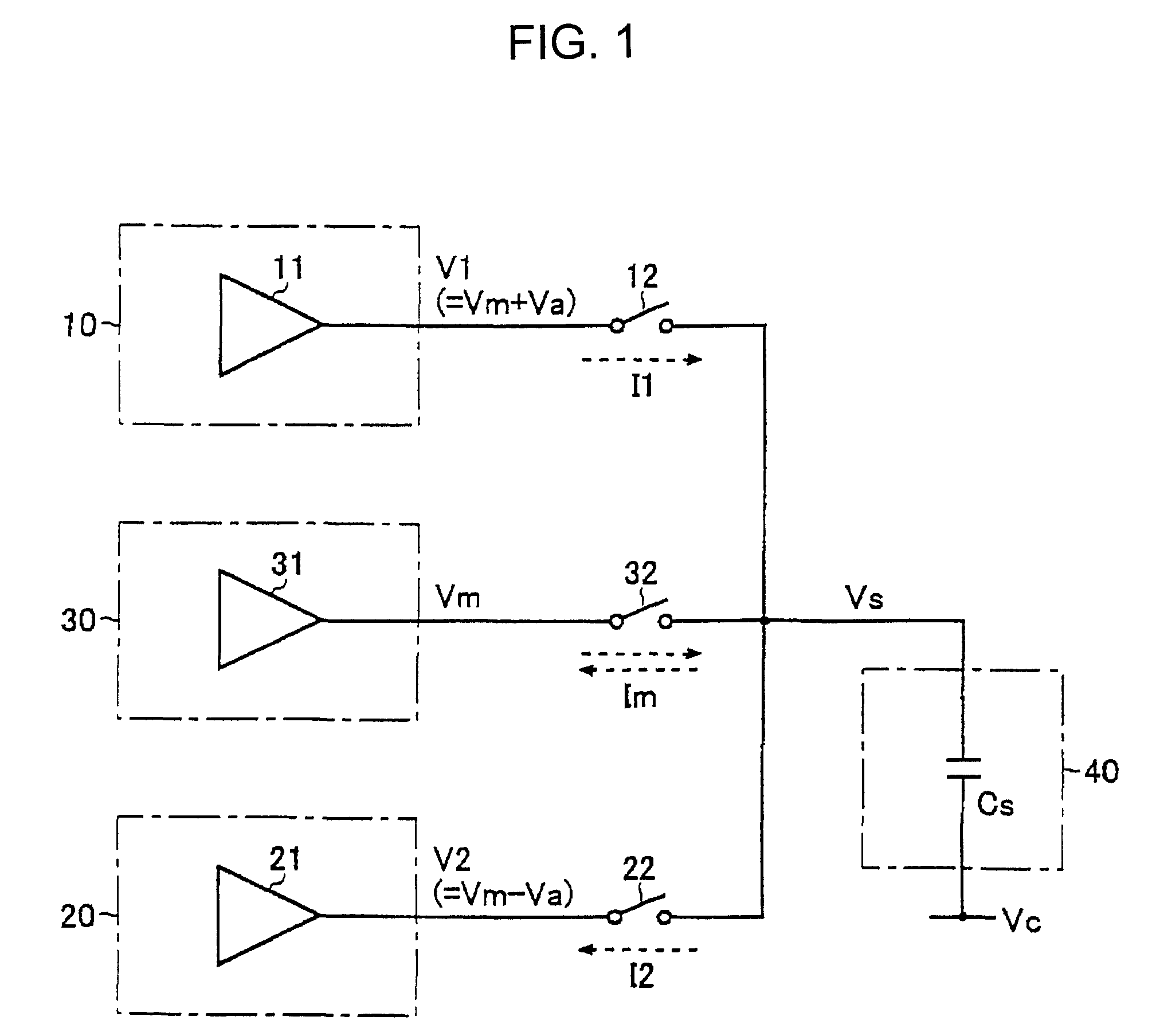
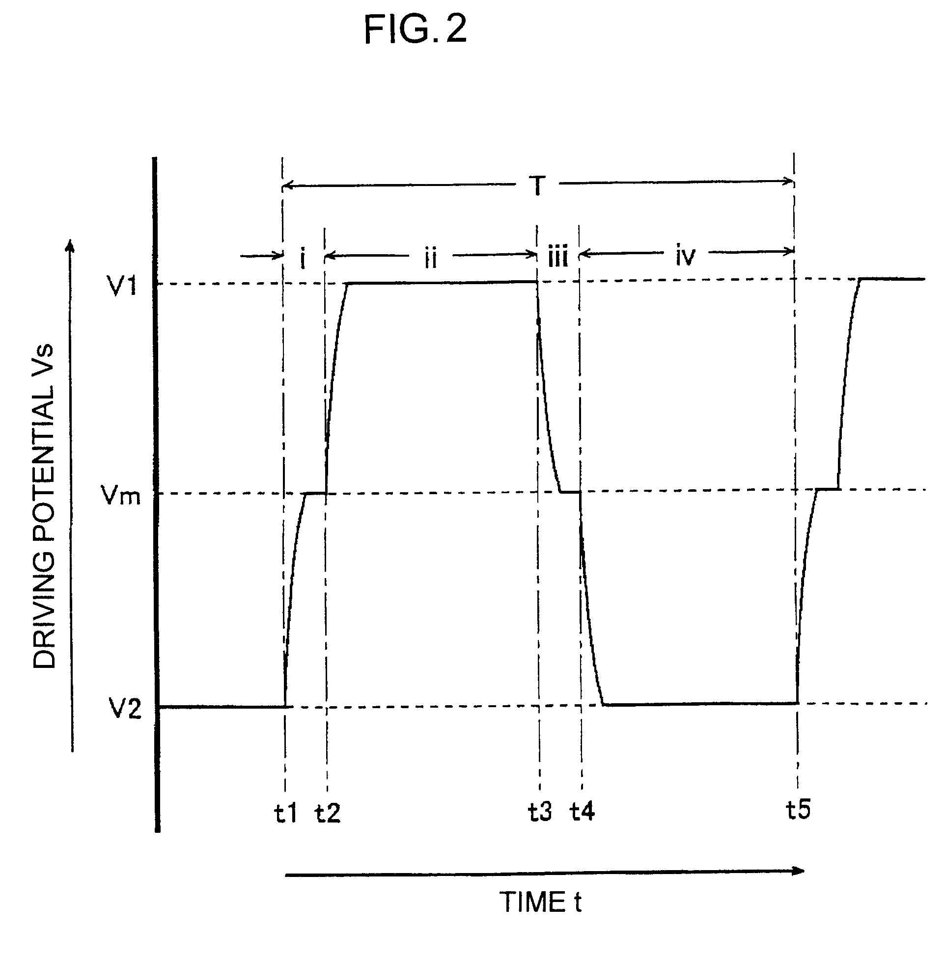
A potential supplied from a capacitive load drive unit to one end of a respective capacitive load is switched to an intermediate potential between a first and a second power supply potentials for a predetermined period of time prior to switching the potential of the one end of the capacitive load from the first to the second power supply potential, or vice versa, which minimizes charging and discharging currents of the load, variations of the potential supplied to the capacitive load, and hence power consumption involved, without providing a charging capacitor having a large capacitance in the capacitive load drive unit.

Description

BACKGROUND OF THE INVENTION[0001]1. Field of the Invention[0002]This invention relates to a method and a drive unit for driving a capacitive load such as a liquid crystal cell at different potentials, and to a liquid crystal display (LCD) utilizing the same.[0003]2. Description of the Related Art[0004]Conventionally, a capacitive load (typically a liquid crystal cell of an LCD) that is driven at different potentials has a structure as shown in FIG. 12 and at the timing as depicted in FIG. 13. As shown in FIG. 12, a typical capacitive load 40 is a liquid crystal cell of an LCD located at a point of intersection of a signal electrode and a scanning electrode of the LCD. The capacitive load 40 has a capacitance Cs.[0005]Supplied to one end of the capacitive load 40 is a driving potential Vs, and to the other end thereof a reference potential Vc. When the capacitive load 40 is a liquid crystal cell, the driving potential Vs serves as a signal potential to be supplied to the signal elect...

Claims


Application Information

Patent Timeline
Patent Type & Authority Patents(United States)
IPC IPC(8): G09G3/36
CPCG09G3/3692H03K19/0016G09G3/2014G09G3/3681G09G2310/0297G09G2310/06G09G2330/023
Inventor MARUO, AKIMASA
Owner ROHM CO LTD
Learn More