Circuit for reducing the variations of auto-supply voltage of a control circuit of a switching power supply

a control circuit and switching power supply technology, applied in the direction of electric variable regulation, power conversion systems, instruments, etc., can solve the problems of fast vcc decrease, worsen system efficiency, and practically impossible to comply with various energystar, energy2000, blue angel, etc., and achieve the effect of simplifying the transformer construction

Active Publication Date: 2011-01-04
STMICROELECTRONICS SRL
View PDF7 Cites 2 Cited by
  • Summary
  • Abstract
  • Description
  • Claims
  • Application Information

AI Technical Summary

Benefits of technology

[0028]This object is also achieved by means of a switching power supply comprising a circuit for reducing the variations of the auto-supply voltage of the control circuit of a switching power supply including a generator of said auto-supply voltage, a controlled switch capable of selectively coupling said generator to said control circuit, and a driving circuit of said controlled switch that supplies a closing signal of said controlled switch after a predefined time delay starting from said deactivation command.
[0029]In addition, this object is achieved by means of a method for reducing the variations of the auto-supply voltage of a control circuit of a switching power supply where said control circuit supplies an activation or deactivation command signal of a power transistor characterised in that it selectively connects the secondary of the transformer of said switching power supply to said control circuit after a predefined delay of time starting from said deactivation command.
[0030]According to the present invention it is possible to produce a circuit capable of minimizing the variations of the auto-supply voltage of control circuits that guarantees safety in functioning in short-circuit conditions (Vcc<Vstop), that facilitates achieving compliance to the regulations regarding consumption of equipment at minimum or negligible load (Vcc>Vstop), that simplifies the construction of the transformer and of the auxiliary winding, and is capable of protecting from overloads in output, that is, capable of turning off the converter when the overload lasts longer than a predefined time.

Problems solved by technology

The increased consumption of the device is not supported by the start-up circuit 11 so that there is a rapid decrease of Vcc.
Another problem is represented by the fact that the voltage Vcc cannot exceed a determined value Vccmax for questions linked to the technology of the integrated control circuit 12 that impose limits to the voltage applicable to it and, at the same time, in conditions of minimum or negligible load, Vcc has to stay greater than Vstop, otherwise the system will function intermittently.
This, however, worsens the efficiency of the system and, above all, makes it practically impossible to comply with the various EnergyStar, Energy2000, Blue Angel, etc.
Nevertheless, if Vccmax is sufficiently high it is not difficult to fulfill the condition at zero load increasing the number of turns of Waux which however, at high load, produces high voltage which, even though tolerable by the integrated circuit, can easily present problems of power dissipation internally (equal to the product Vcc·Iq), without taking into account the fact that a high Vccmax entails the use of costly technology.
If Vstop is very low (compatibly with the safety limits for driving the MOSFETs) it will be easier to fulfill the zero load condition, however it will be difficult to fulfill the condition on the short circuit.
At very low or negligible load, however, it cannot keep the Vcc stable, that decreases considerably, worse than in the case of the circuit of FIG. 1.

Method used


Image

  • Circuit for reducing the variations of auto-supply voltage of a control circuit of a switching power supply
  • Circuit for reducing the variations of auto-supply voltage of a control circuit of a switching power supply
  • Circuit for reducing the variations of auto-supply voltage of a control circuit of a switching power supply

Examples


Embodiment Construction

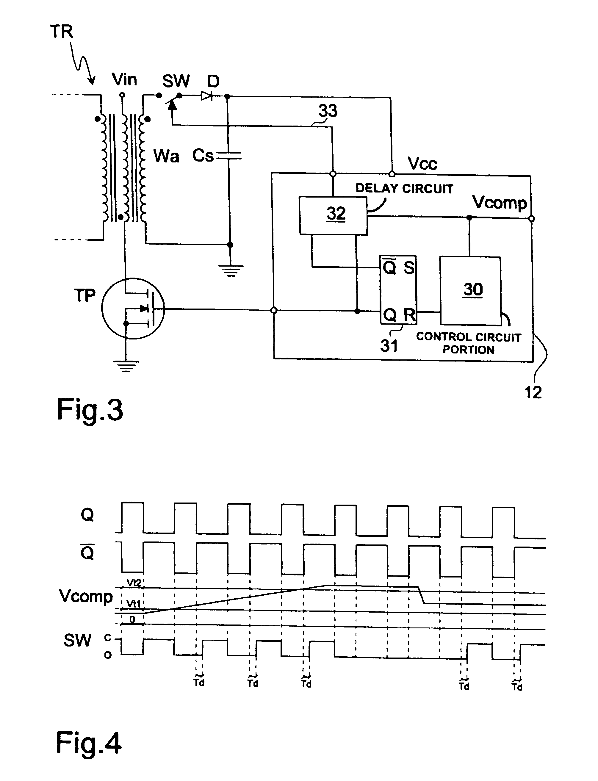
[0038]FIG. 3 shows the transformer TR of a switching power supply fed by the voltage Vin, and connected to a power transistor TP. A terminal of the secondary Wa of the transformer TR is connected to a controlled switch SW, then to a diode D and to a terminal of a capacitor Cs. The voltage at the terminals of the capacitor Cs is the supply voltage Vcc of the integrated control circuit 12.

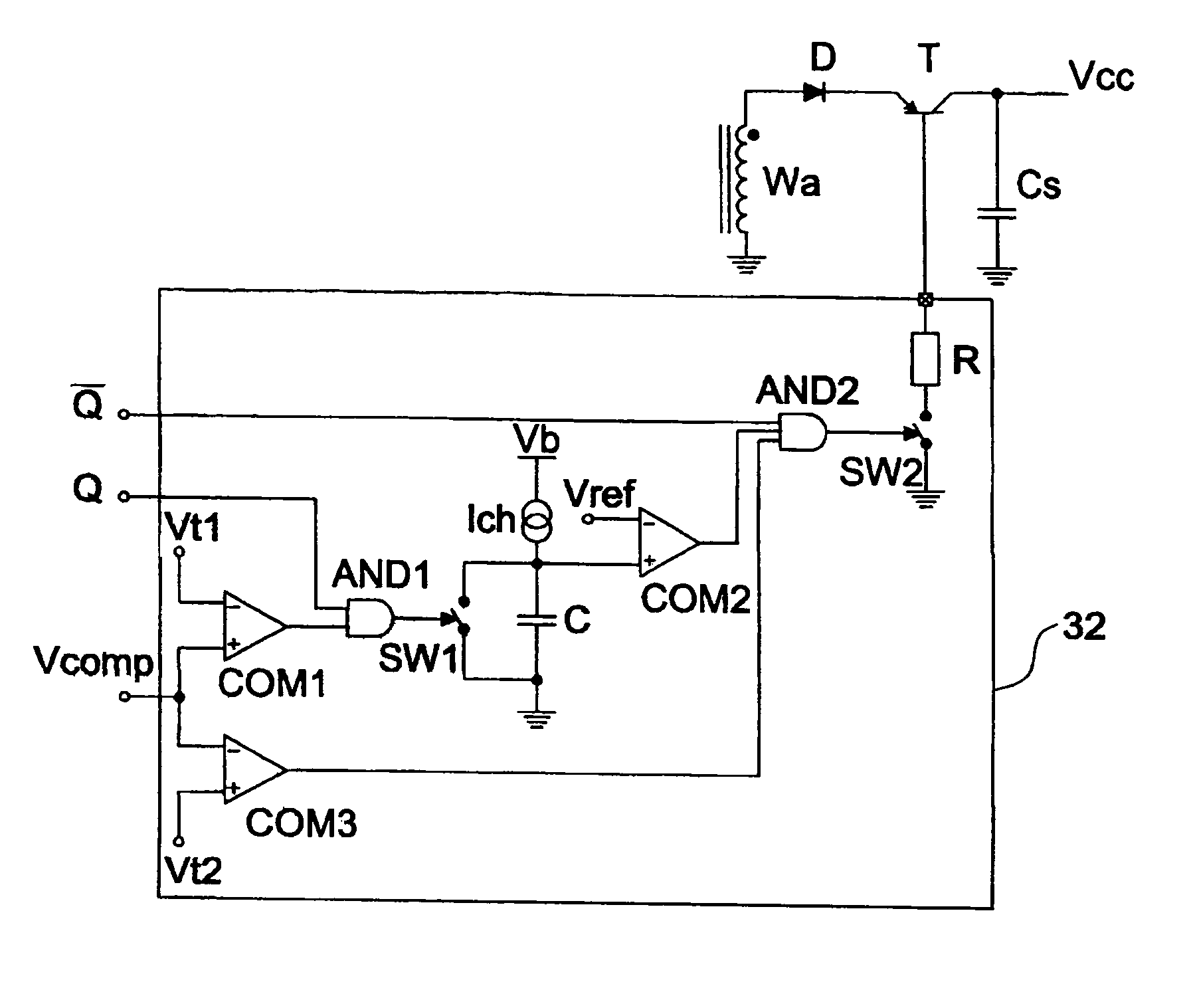
[0039]The integrated control circuit 12 comprises a circuit 30 for managing it to which is connected a circuit FLIP-FLOP 31 that supplies the command signal Q (and Q-negated) for driving the transistor TP. The signals Q and Q-negated are supplied to a delay circuit 32. A signal Vcomp is also supplied to this circuit.

[0040]The voltage Vcomp is the voltage at the output of the error amplifier, used in the power supply, and that is commonly indicated as “control voltage”, as it controls the power supply determining the values of the turn-on and turn-off times of the power transistor TP. Said voltage, wi...


PUM


Abstract

A circuit for reducing the variations of auto-supply voltage of a control circuit of a switching power supply, where the control circuit supplies an activation or deactivation signal of a power transistor, includes an auto-supply voltage generator, a controlled switch capable of selectively connecting the generator to the control circuit, and a driving circuit of the controlled switch that supplies a closing signal of the controlled switch after a predefined delay of time starting from the deactivation command.

Description

RELATED APPLICATION[0001]The present application is a U.S. national filing and claims priority of PCT / EP2005 / 050737 filed Feb. 21, 2005, which claims priority of Italian Patent Application No. MI2004A000383 filed Mar. 2, 2004, both of which applications are incorporated herein in their entireties by this reference.FIELD OF THE INVENTION[0002]The present invention refers to switching power supplies and in particular to a circuit for reducing the variations of auto-supply voltage of a control circuit of a switching power supply.[0003]More precisely, it refers to a method and to a circuit, to be made completely or partially in an integrated form, applicable to pulse width modulation (PWM) integrated control circuits, used in network converters.BACKGROUND[0004]Network converters such as those described above, are fitted with a transformer and a switch (typically MOSFET) that periodically connects a transformer winding to the input source, that is to a network voltage rectified by a diod...

Claims


Application Information

Patent Timeline
Patent Type & Authority Patents(United States)
IPC IPC(8): H02M7/5383H02M3/335H02M3/28
CPCH02M3/28H02M2001/0006H02M2001/009H02M1/0006H02M1/009
Inventor ADRAGNA, CLAUDIOFAGNANI, MAURO
Owner STMICROELECTRONICS SRL
Why Eureka
Try Eureka