
Test generation methods for reducing power dissipation and supply currents

a technology of power dissipation and supply current, applied in the field of generating test patterns, can solve the problems of excessive switching activity, excessive switching, and high switching activity on the integrated circuit, and achieve the effect of reducing peak power, average power dissipation and/or supply current, and reducing power during testing

Active Publication Date: 2011-01-04
SIEMENS PROD LIFECYCLE MANAGEMENT SOFTWARE INC
View PDF11 Cites 10 Cited by
  • Summary
  • Abstract
  • Description
  • Claims
  • Application Information

AI Technical Summary

Benefits of technology

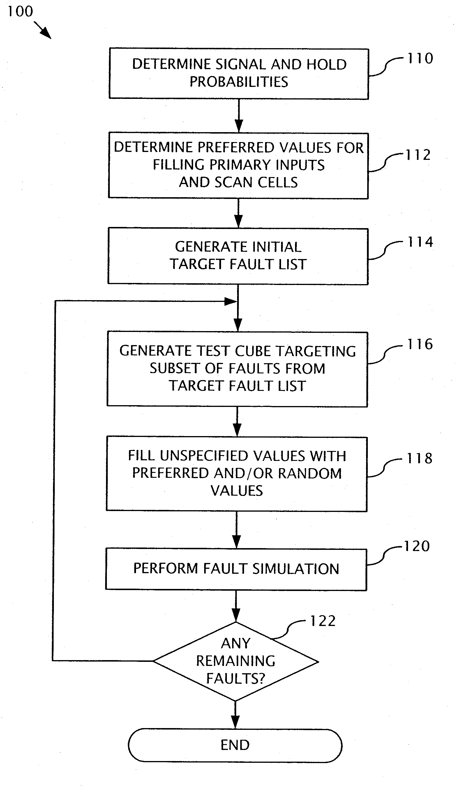
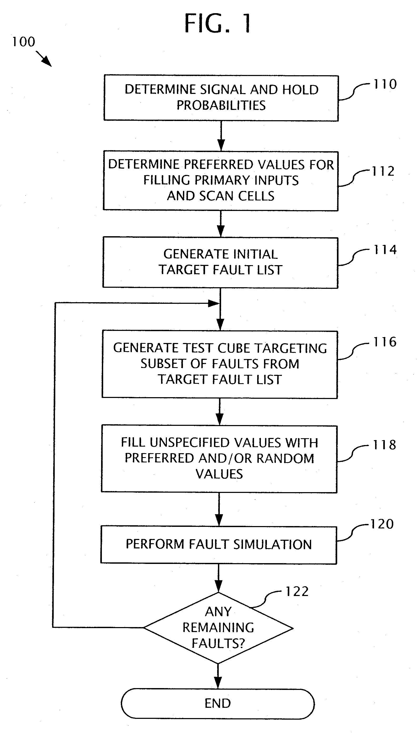
[0004]Disclosed below are representative embodiments of methods, apparatus, and systems used for generating test patterns as may be used as part of a test pattern generation process (for example, for use in an automatic test pattern generator (ATPG) software tool). Embodiments of the disclosed technology can provide a scalable test generation method that reduces peak power, average power dissipation, and / or supply currents during the capture cycles of scan tests. In particular embodiments, the same test coverage as traditional test strategies can be achieved while reducing power during testing. In certain desirable embodiments of the disclosed technology, no additional hardware is required. Furthermore, existing test generation tools can support embodiments of the disclosed technology with only minor modification.
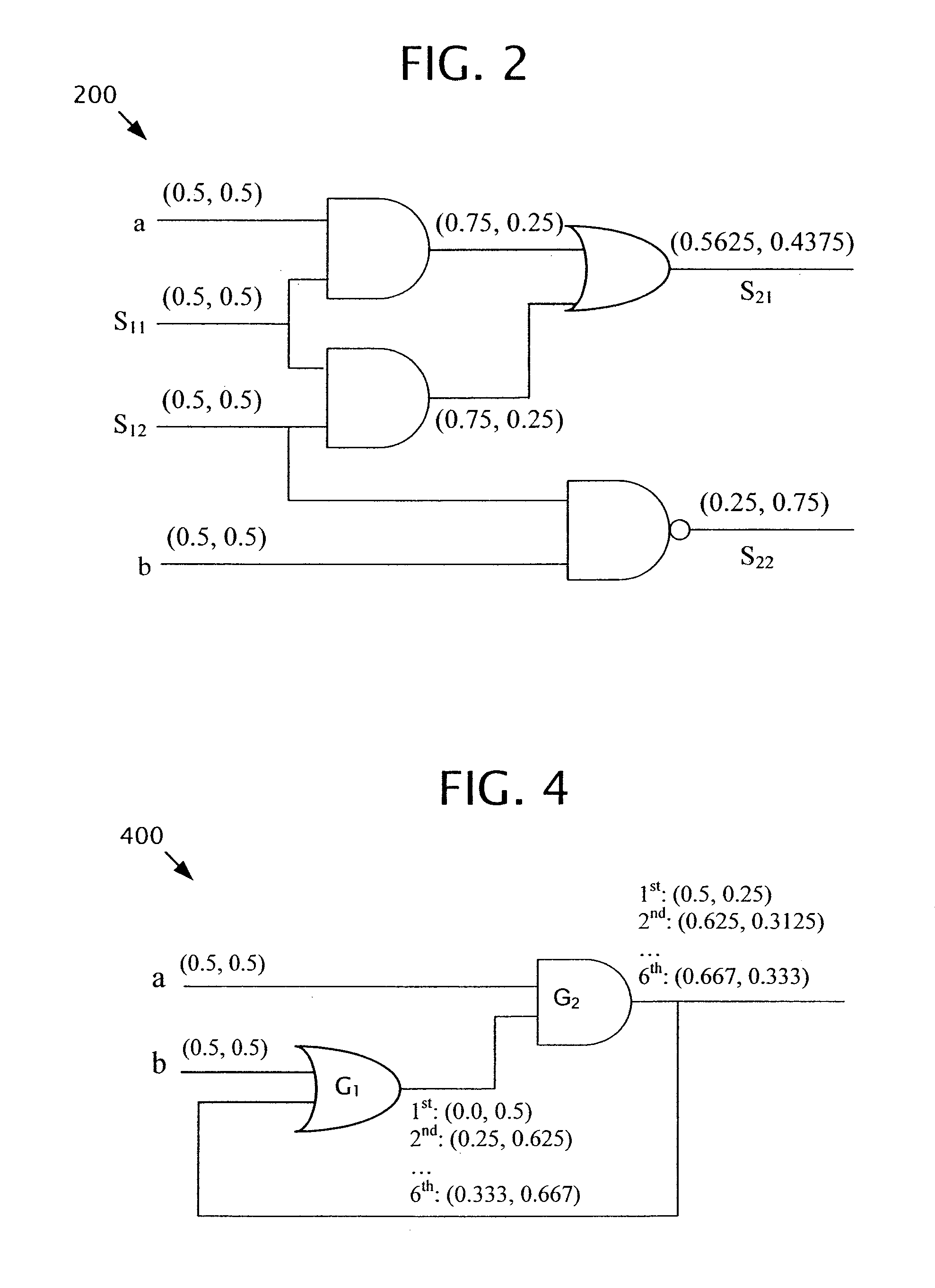
[0005]In one disclosed embodiment, signal and hold probabilities derived from the circuit are used to guide the filling of unspecified values in test cubes. The signal and hold probabilities can be computed, for example, before test generation. Unspecified values in a test cube can be filled simultaneously (or substantially simultaneously), making the exemplary method scalable with circuit size. In general, the time to compute the signal and hold probabilities is linearly proportional to the number of gates in the design. Thus, the running time overhead due to the signal / hold probability computation is negligible. In further embodiments described herein, power consumption is reduced by using probabilities to guide test cube generation without losing test coverage.
[0008]Also described herein are methods for selecting preferred values filled at primary inputs and / or scan cells based on the results of the probability calculations. The selection methods can help reduce power dissipation and supply currents during capture cycles. Moreover, any of the filling procedures described herein can be performed simultaneously or substantially simultaneously. For instance, according to one exemplary implementation, all unspecified values in the test cube are filled simultaneously or substantially simultaneously.
[0013]In another exemplary method of generating test patterns, one or more faults to target are selected from a fault list, and a first set of test pattern values that target the one or more selected faults is generated. A second set of test pattern values that reduces power consumption in the integrated circuit design during testing is also generated. In this embodiment, the second set of test pattern values is determined at least in part from probability values indicating whether one or more state elements (for example, scan cells) in the integrated circuit design will output constant logic values over two or more consecutive clock cycles. A test pattern comprising at least the first set of test pattern values and the second set of test pattern values is stored. In certain implementations, the second set of test pattern values causes no transitions to occur at one or more of the state elements of the integrated circuit design during a capture cycle of testing. In some implementations, the exemplary method further comprises generating a third set of test pattern values, which comprises randomly selected values. The third set of test pattern values can also be stored as part of the test pattern. In particular implementations, the third set of test pattern values is generated before the second set of test pattern values but after the first set of test pattern values. Furthermore, in some implementations, the third set of test pattern values is generated for a predetermined percentage of the remaining test pattern values to be specified after the first set of test pattern values is generated. In particular implementations, signal probabilities for the one or more logic gates are also determined. For example, a respective one of the signal probabilities can indicate the probability that a respective logic gate will have either a logic 0 or a logic 1 value. The probability values indicating whether one or more state elements in the integrated circuit design will output constant logic values over two or more consecutive clock cycles can be determined using the signal probabilities. In certain implementations, the method further comprises simulating the test pattern to determine which faults of the fault list are detected by the test pattern, updating the fault list to remove the faults that are detected by the test pattern, and repeating the acts of selecting, generating the first portion, generating the second portion, and storing the test pattern using the updated fault list.

Problems solved by technology

The scan tests generated by a typical ATPG tool, however, can create switching activity on the integrated circuit that far exceeds the activity present during normal operation of the circuit.
Furthermore, excessive switching activity can occur during several stages of the testing operation.
For example, excessive switching can occur when the scan chain is loading a test pattern, unloading a test response, or when its scan cell contents are updated during the capture cycles (for example, when the scan cells are clocked by one or more functional clocks).
Abnormal switching activity can create an abnormal peak power dissipation, an abnormal average power dissipation, and / or undesirable supply currents.
Excessive power dissipation can create hot spots that could damage the CUT.
Furthermore, excessive peak supply currents can cause supply voltage drops that result in increased gate delays during testing.
Such gate delays during testing may cause good chips to fail (for instance, to fail at-speed tests) and cause unnecessary yield loss.

Method used


Image

  • Test generation methods for reducing power dissipation and supply currents
  • Test generation methods for reducing power dissipation and supply currents
  • Test generation methods for reducing power dissipation and supply currents

Examples


Embodiment Construction

[0031]Disclosed below are representative embodiments of methods, apparatus, and systems used for generating test patterns as may be used as part of a test pattern generation process (for example, for use with an automatic test pattern generator (ATPG) software tool). The disclosed methods, apparatus, and systems should not be construed as limiting in any way. Instead, the present disclosure is directed toward all novel and nonobvious features and aspects of the various disclosed methods, apparatus, systems, and equivalents thereof, alone and in various combinations and subcombinations with one another. The present disclosure is not limited to any specific aspect or feature, or combination thereof, nor do the disclosed methods, apparatus, and systems require that any one or more specific advantages be present or problems be solved.

[0032]Although the operations of some of the disclosed methods, apparatus, and systems are described in a particular, sequential order for convenient prese...


PUM


Abstract

Disclosed herein are representative embodiments of methods, apparatus, and systems used for generating test patterns as may be used as part of a test pattern generation process (for example, for use with an automatic test pattern generator (ATPG) software tool). In one exemplary embodiment, hold probabilities are determined for state elements (for example, scan cells) of a circuit design. A test cube is generated targeting one or more faults in the circuit design. In one particular implementation, the test cube initially comprises specified values that target the one or more faults and further comprises unspecified values. The test cube is modified by specifying at least a portion of the unspecified values with values determined at least in part from the hold probabilities and stored.

Description

CROSS REFERENCE TO RELATED APPLICATION[0001]This application is a continuation of U.S. Patent Application No. 11 / 784,460, filed Apr. 5, 2007, now U.S. Pat. No. 7,685,491 and entitled “TEST GENERATION METHODS FOR REDUCING POWER DISSIPATION AND SUPPLY CURRENTS,” which claims the benefit of U.S. Provisional Patent Application No. 60 / 789,687, filed Apr. 5, 2006, and entitled “TEST GENERATION METHODS FOR REDUCING POWER DISSIPATION AND SUPPLY CURRENTS,” the contents of both of which are hereby incorporated herein by reference.FIELD[0002]This application relates generally to the field of testing integrated circuits, and more particularly to the field of generating test patterns for use during integrated circuit testing.BACKGROUND[0003]The use of automatic test pattern generation (ATPG) to generate test patterns for scan-based or partially-scan-based integrated circuits is quite common. The scan tests generated by a typical ATPG tool, however, can create switching activity on the integrated...

Claims


Application Information

Patent Timeline
Patent Type & Authority Patents(United States)
IPC IPC(8): G01R31/28G06F11/00
CPCG01R31/31721G01R31/318357G01R31/318575
Inventor LIN, XIJIANGRAJSKI, JANUSZ
Owner SIEMENS PROD LIFECYCLE MANAGEMENT SOFTWARE INC
Learn More