
Composite plate comprising carbon nanotube bundles with high thermal conductivity and method for making the same

Active Publication Date: 2011-01-11
ROCKWELL COLLINS INC +1
View PDF7 Cites 9 Cited by
  • Summary
  • Abstract
  • Description
  • Claims
  • Application Information

AI Technical Summary

Benefits of technology

[0005]Accordingly, the present invention is directed to a composite plate comprising CNT bundles with high thermal conductivity and the method of making the same. The method of forming the composite plate comprising CNT bundles with high thermal conductivity comprises preparing a CNT growth substrate, depositing a CNT growth catalyst on the CNT growth substrate, preparing a wafer with etched through via arrays, placing the wafer with the etched through via arrays over the CNT growth substrate with the CNT growth catalyst, growing CNT bundles in the etched through via arrays on the wafer over the CNT growth substrate with the CNT growth catalyst in a CVD chamber to form a wafer matrix CNT composite structure; and removing the CNT growth substrate from the wafer matrix CNT composite structure. The formed composite plate comprising CNT bundles with high thermal conductivity provides and improved CTE silicon match, provides a more effective thermal conductivity than a silicon matrix or Cu or Cu alloy substrate, and contains nanotubes that remain vertical.

Problems solved by technology

Typically, copper (Cu) and Cu alloys are utilized as the thermal conductive substrate in silicon chips in high power device applications where junction temperature is limiting the device performance.
However the CNT bundles have poor adhesion to the substrate.
Therefore, when CNT bundles reach more than 100 micrometers in length, they have difficulty in remaining upright.
These difficulties have prevented the application of the CNT bundles, which have extremely high thermal conductivity, to macroscopic thermal management, such as silicon chip for high power device applications, in any meaningful way.

Method used


Image

  • Composite plate comprising carbon nanotube bundles with high thermal conductivity and method for making the same
  • Composite plate comprising carbon nanotube bundles with high thermal conductivity and method for making the same
  • Composite plate comprising carbon nanotube bundles with high thermal conductivity and method for making the same

Examples


Embodiment Construction

[0016]Reference will now be made in detail to the presently preferred embodiments of the invention, examples of which are illustrated in the accompanying drawings.

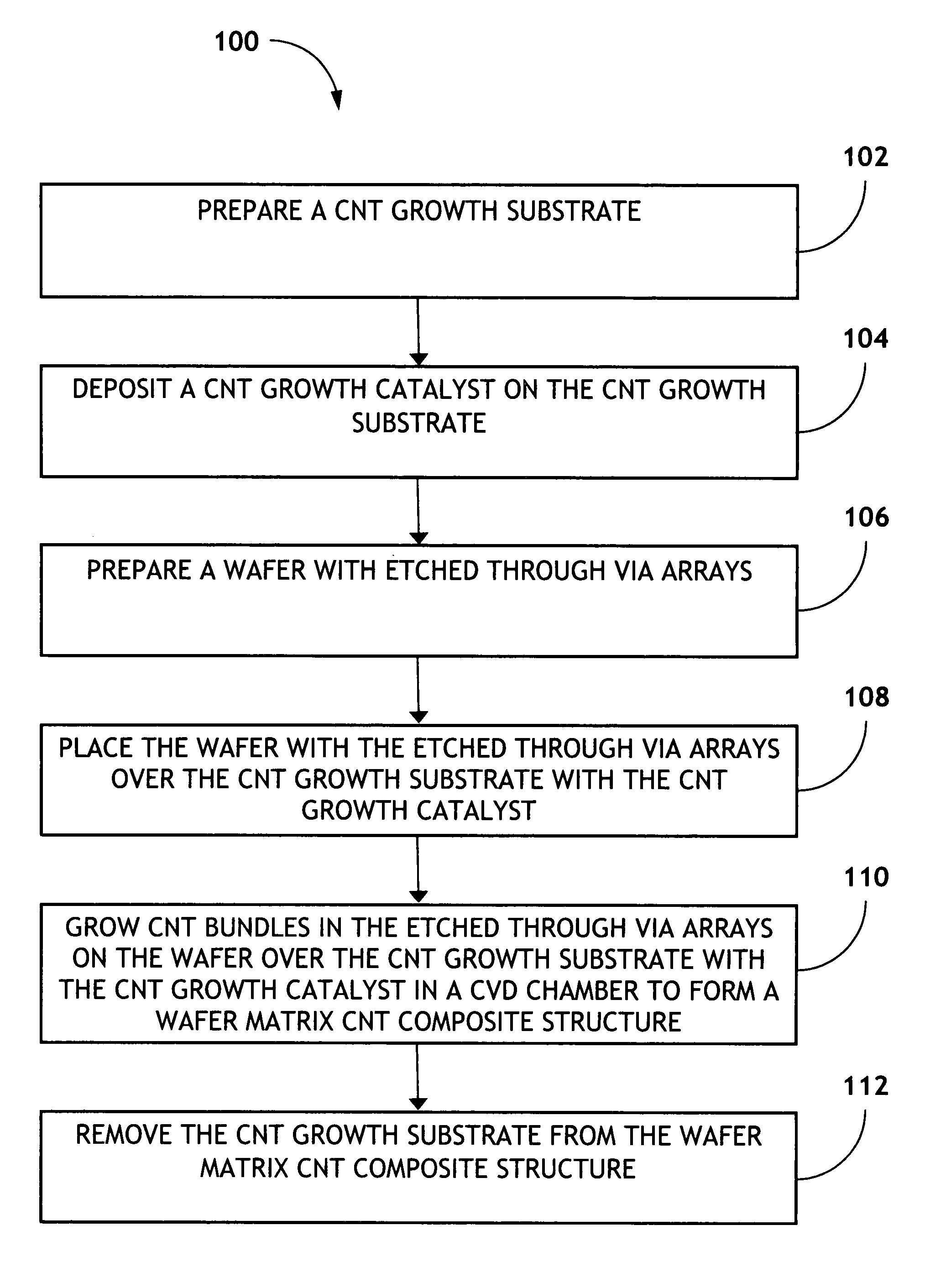
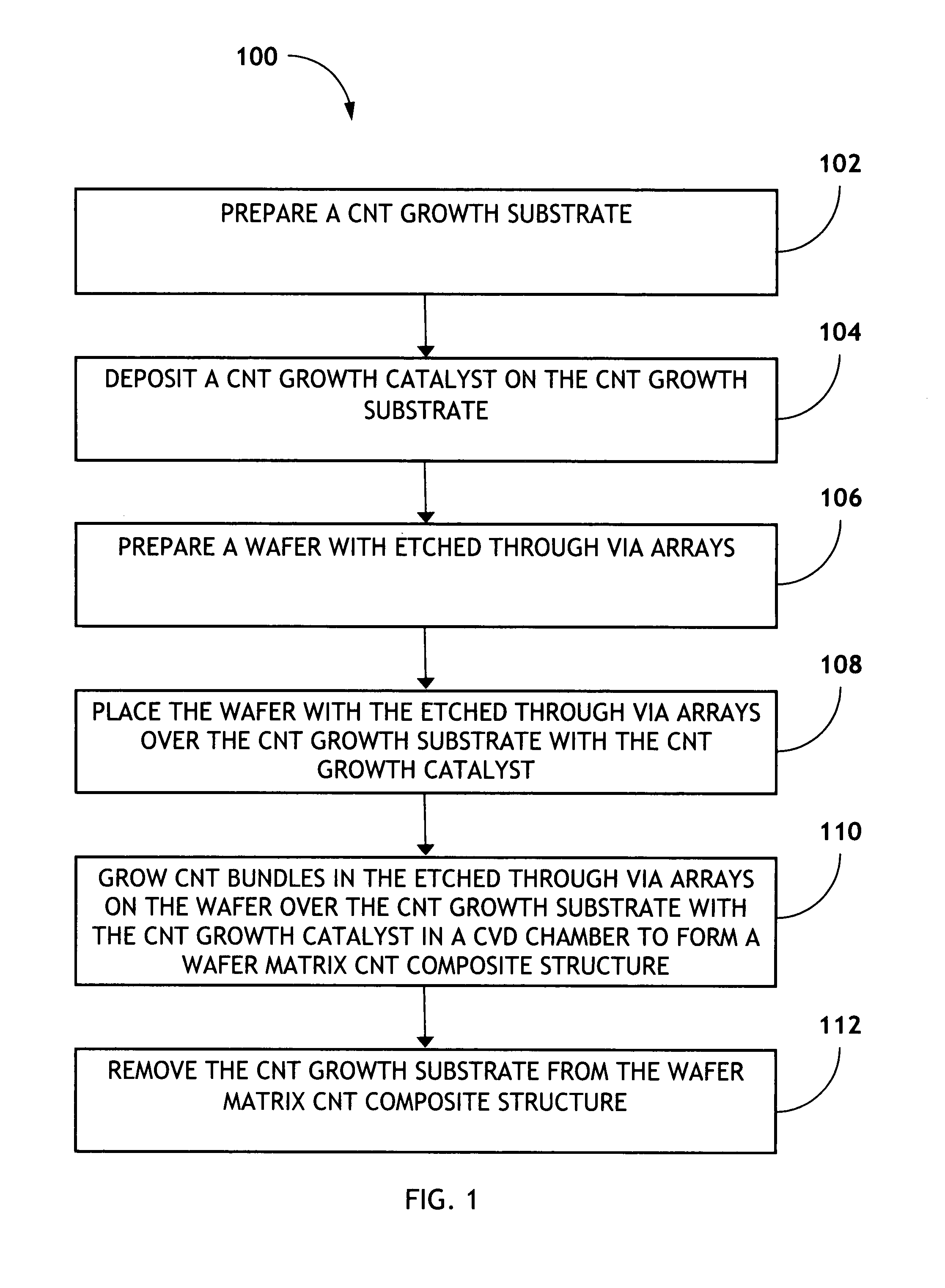
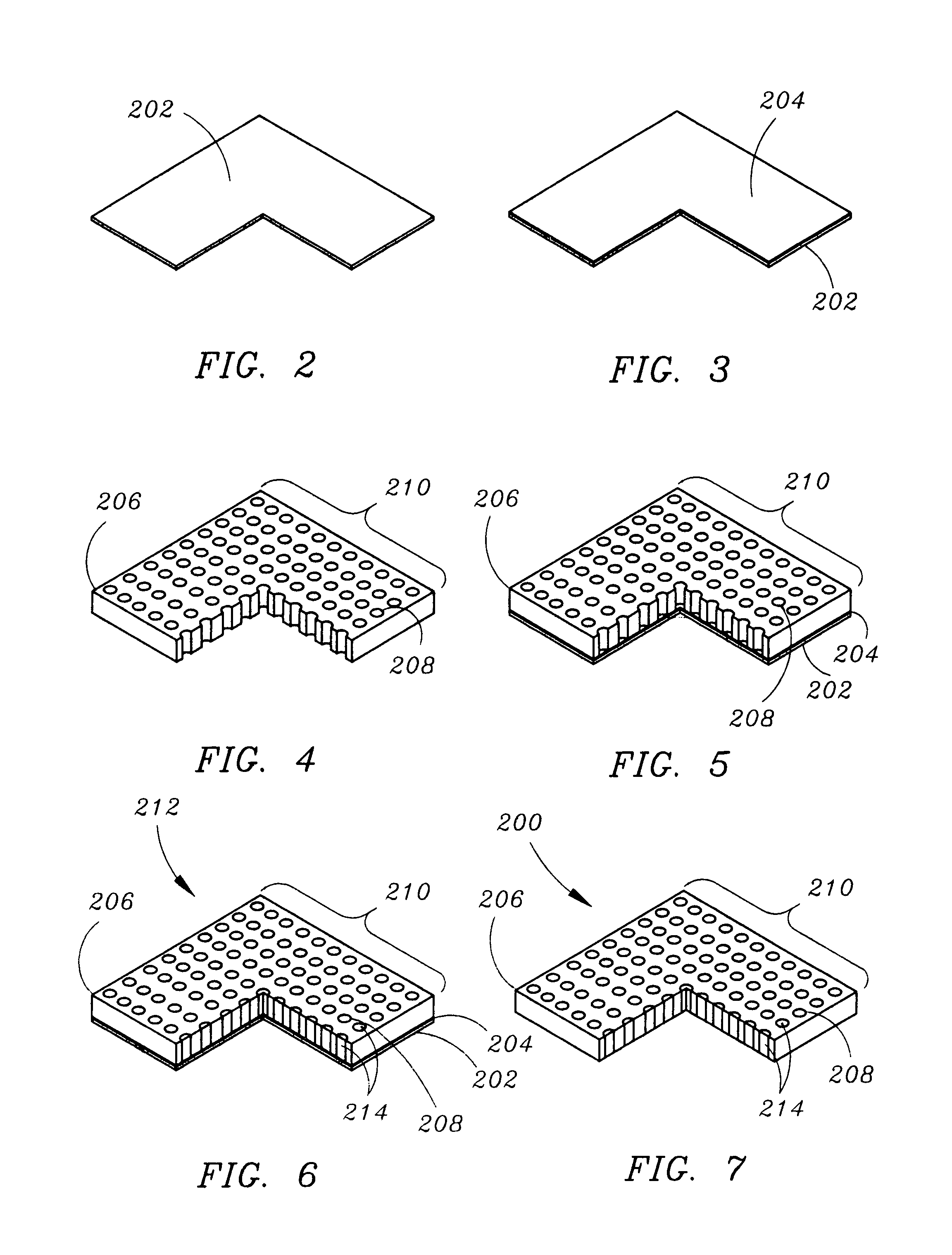
[0017]Referring to FIG. 1, a flow diagram illustrating a method for producing a composite plate comprising CNT bundles with high thermal conductivity 100 is shown in accordance with exemplary embodiments of the present invention. Method 100 begins with preparation of a CNT growth substrate, 102. Referring to FIG. 2, a cross-sectional isometric view illustrating a CNT growth substrate 202 is shown in accordance with exemplary embodiments of the present invention. The CNT growth substrate 202 is thin and flat. The CNT growth substrate 202 may be AlN, Al2O3, or any other suitable CNT growth substrate 202.

[0018]Method 100 deposits a CNT growth catalyst on the CNT growth substrate, 104. Referring to FIG. 3, a cross-sectional isometric view illustrating a CNT growth catalyst 204 on the CNT growth substrate 202 is shown in accord...


PUM

PropertyMeasurementUnit
Fractionaaaaaaaaaa
Thermal conductivityaaaaaaaaaa

Abstract

A composite plate comprising CNT bundles with high thermal conductivity is formed by the method comprising preparing a CNT growth substrate, depositing a CNT growth catalyst on the CNT growth substrate, preparing a wafer with etched through via arrays, placing the wafer with the etched through via arrays over the CNT growth substrate with the CNT growth catalyst, growing CNT bundles in the etched through via arrays on the wafer over the CNT growth substrate with the CNT growth catalyst in a CVD chamber to form a wafer matrix CNT composite structure; and removing the CNT growth substrate from the wafer matrix CNT composite structure. The formed composite plate comprising CNT bundles with high thermal conductivity has improved CTE silicon match, has a more effective thermal conductivity than a silicon matrix or Cu or Cu alloy substrate, and contains nanotubes that remain vertical.

Description

FIELD OF THE INVENTION[0001]The present invention generally relates to the field of macroscopic thermal management, and more particularly to a thermal conductive substrate in a silicon chip, such as a silicon-carbon nanotube composite plate.BACKGROUND OF THE INVENTION[0002]Typically, copper (Cu) and Cu alloys are utilized as the thermal conductive substrate in silicon chips in high power device applications where junction temperature is limiting the device performance.[0003]Carbon nanotubes (CNTs) are known for their ballistic electric and thermal transport properties. For example, the theoretical thermal conductivity of a single walled CNT is 6,000 Watt / ((meter)(Kelvin)), while the thermal conductivity for a diamond is 2,000 W / ((m)(K)). A single walled CNT has been measured in a lab to be 3,000 W / ((m)(K)). A multi-walled CNT should have a higher thermal conductivity because the wall layers when the end cap is removed may act as parallel channels transporting more valence electron t...

Claims


Application Information

Patent Timeline
IPC IPC(8): B32B9/04B32B15/04B32B13/04
CPCB82Y30/00B82Y40/00C23C16/042C23C16/26Y10T428/30Y10S977/742Y10S977/781
Inventor YAO, OIZHOUJONES, ALLEN W.LANDT, DON L.LEHTOLA, GARY E.
Owner ROCKWELL COLLINS INC
Learn More