Quantum cryptography key distributing system and synchronizing method used in the same

a technology of quantum cryptography and synchronization method, which is applied in the direction of instruments, digital transmission, secret communication, etc., can solve the problems that the optical pulse to be sent out from the bob to the alice cannot be controlled at all, and the plug & play system cannot be realized

Active Publication Date: 2011-01-11
NEC CORP
View PDF24 Cites 15 Cited by
  • Summary
  • Abstract
  • Description
  • Claims
  • Application Information

AI Technical Summary

Problems solved by technology

However, the quantum cryptography key distributing system is largely different from a conventional optical communication system in that a clock signal cannot be extracted by using a quantum channel, unlike the conventional optical communication, since the optical power of this quantum cryptography key distributing system is very weak to an extent of a single photon level.
However, the quantum cryptography key distributing system is largely different from the conventional optical communication systems in that a clock signal cannot be extracted by using a quantum channel, since the optical power in the quantum cryptography key distributing system is very weak as much as a single photon level.
However, the optical pulses to be sent out from the Bob to the Alice cannot be controlled at all.
Therefore, the Plug & Play system cannot be realized.

Method used


Image

  • Quantum cryptography key distributing system and synchronizing method used in the same
  • Quantum cryptography key distributing system and synchronizing method used in the same
  • Quantum cryptography key distributing system and synchronizing method used in the same

Examples


Embodiment Construction

[0051]Hereinafter, a quantum cryptography key distributing system will be described in detail with reference to the attached drawings.

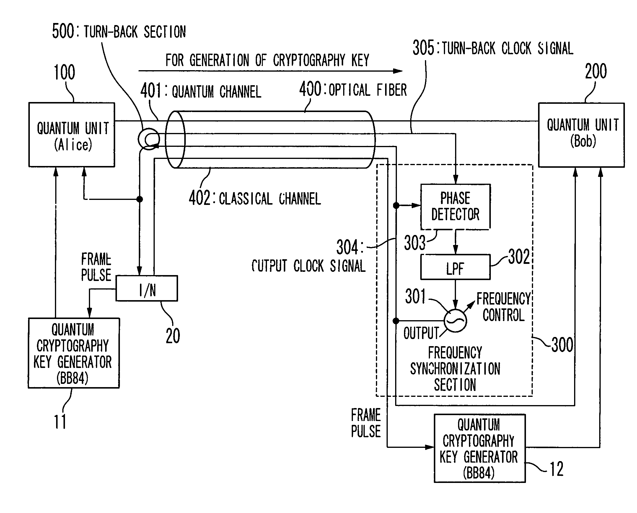
[0052]FIG. 4 is a schematic block diagram showing the configuration of the quantum cryptography key distributing system according to the first embodiment of the present invention. In FIG. 4, the quantum cryptography key distributing system in the first embodiment is composed of a quantum unit 100 as a transmission end to be referred to as “Alice” hereinafter, another quantum unit 200 of a reception end to be referred to as “Bob” hereinafter, and an optical fiber 400. The Bob contains a frequency synchronizing unit 300, and the Alice contains a turn back section 500. The optical fiber 400 provides a transfer path that connects the Alice 100 and the Bob 200 with each other. Both of the Alice 100 and the Bob 200 cooperate to generate a cryptography key via a quantum channel 401 of the optical fiber 400. The frequency synchronizing unit 300 is composed of...


PUM


Abstract

A quantum cryptography key distributing system includes an optical fiber; a transmission unit and a reception unit. The transmission unit is connected with the optical fiber, generates a transmission optical pulse signal from an optical pulse signal based on a first data in synchronism with an optical clock signal and transmits the transmission optical pulse signal to the reception unit via the optical fiber. Polarization of the transmission optical pulse signal is different from that of the optical pulse signal. The reception unit is connected with the optical fiber, transmits the optical pulse signal to the transmission unit via the optical fiber, phase-modulates a part of the transmission optical pulse signal based on a second data in synchronism with the optical clock signal, and detects a reception data corresponding to the first data based on the transmission optical pulse signal in synchronism with the optical clock signal.

Description

BACKGROUND OF THE INVENTION[0001]1. Field of the Invention[0002]The present invention relates to a quantum cryptography key distributing system and a synchronizing method used in the same.[0003]2. Description of the Related Art[0004]A quantum cryptography key distributing system can detect optical interception (eavesdropping) in a high probability in communication between a transmitter unit (to be referred to as “Alice” hereinafter) and a receiver unit (to be referred to as “Bob” hereinafter) based upon the uncertainty principle by Heisenberg. Therefore, whether or not a distributed key is safe can be clearly confirmed. In other words, in the quantum cryptography key distributing system, it is possible to achieve higher security by using the distributed safe key as a key of Vernam cryptography in which absolute security is proved.[0005]Next, as an example of distribution of a shared key in a quantum cryptography key distributing system, a case that phase interference (BB84: Bennett ...

Claims


Application Information

Patent Timeline
Patent Type & Authority Patents(United States)
IPC IPC(8): H04K1/00H04L9/00G01B9/02H04L9/12H04L9/08
CPCH04B10/70H04L9/0858H04L9/12
Inventor TAJIMA, AKIO
Owner NEC CORP
Why Eureka
Try Eureka