Density and viscosity sensor

a density and viscosity sensor and density sensor technology, applied in the direction of instruments, specific gravity measurement, measurement devices, etc., can solve the problems of high intrusion of measuring devices, limited accuracy of such devices, and a typical size of several centimeters of transducers, so as to improve the displacement to volume ratio and reduce the measurement time.

Active Publication Date: 2011-01-25
SCHLUMBERGER TECH CORP
View PDF12 Cites 40 Cited by
  • Summary
  • Abstract
  • Description
  • Claims
  • Application Information

AI Technical Summary

Benefits of technology

[0042]Consequently, the sensor of the invention enables overcoming the temperature and pressure effect on the beam material. Using at least two vibration modes with different coupling equations with the fluid enables computation of density and viscosity independently from pressure and temperature. Two sensors each using a vibrating mode with different coupling with the fluid may also be possible.
[0043]The use of a high piezoelectric disk to membrane surface ratio, enables operation of the sensor at high pressure.
[0045]The sensor of the invention improves greatly the displacement to volume ratio allowing efficient resonator excitation without generating acoustic wave in the fluid, thus overcoming the microphonic effect.
[0046]Finally, the measurement method of the invention allows a drastic reduction of the measurement time by using a broadband excitation signal covering the full range of useful frequency.

Problems solved by technology

This transducer has a typical size of several centimeters requiring a bulky and expensive sensor housing.
This leads to a highly intrusive measuring device preventing its use in small sample chambers or small pipes.
Accuracy of such device is limited by pressure and temperature effects on the sensor materials requiring adding complementary pressure and temperature sensors for corrections.
Operation at high pressure and high temperature is also very difficult to implement due to the large size and due to the piezoelectric transducer elements implementation inside the sensor housing.
Further the sensor geometry does not allow to align the sensing element with the flow leading to large measurement perturbations at high fluid velocities.

Method used


Image

  • Density and viscosity sensor
  • Density and viscosity sensor
  • Density and viscosity sensor

Examples


first embodiment

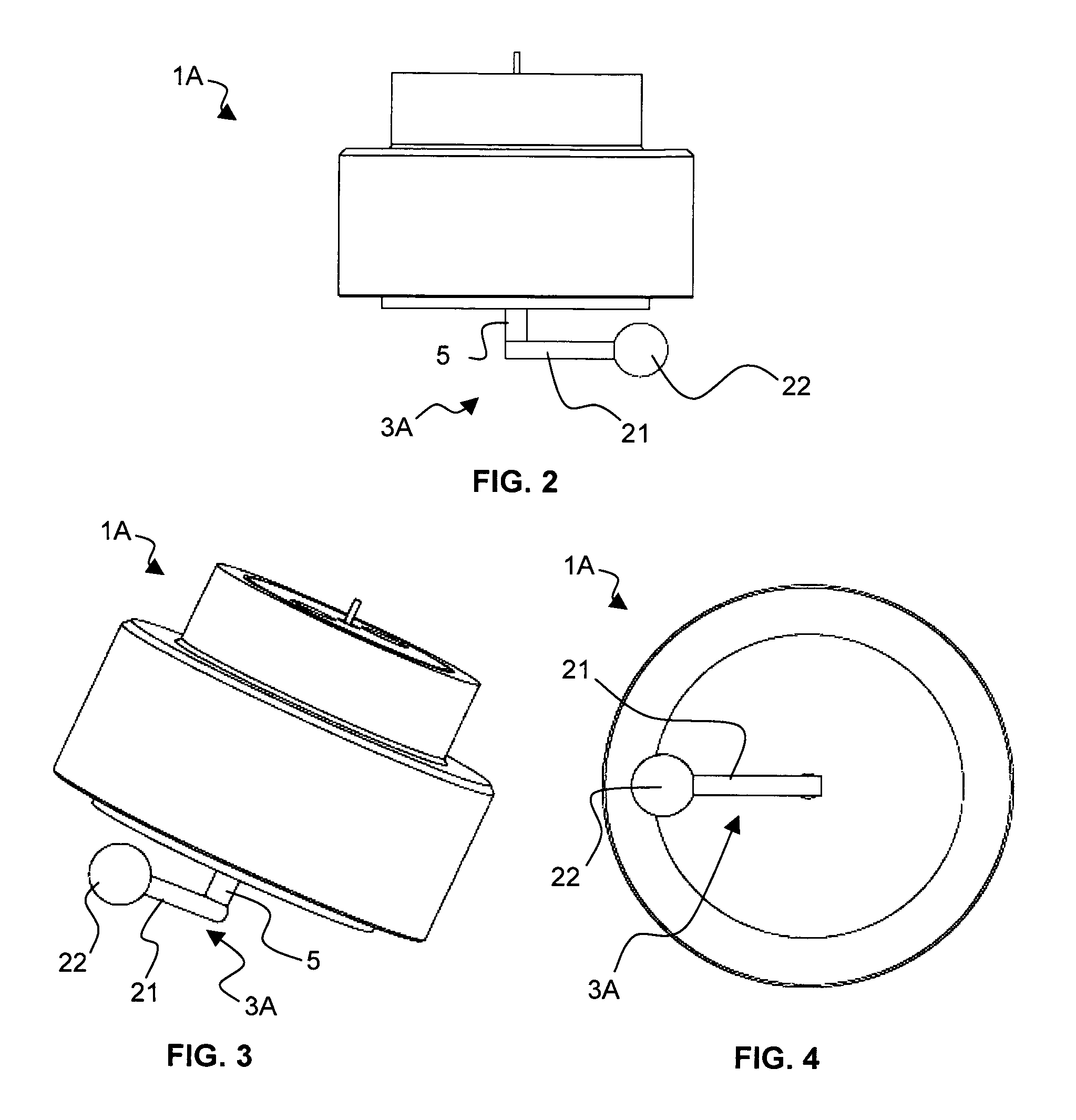
[0077]FIGS. 2, 3 and 4 are side, perspective and bottom views schematically showing a sensor for measuring density and viscosity of a fluid 1A of the invention, respectively. In this embodiment, the resonating element 3A is under the form of a beam 21, substantially straight, attached at one end to the housing 2 by the mechanical coupling element 5 and comprising, at the other end, a spherical mass 22. The beam 21 is made of a wire having a circular cross-section or an elliptical cross-section.

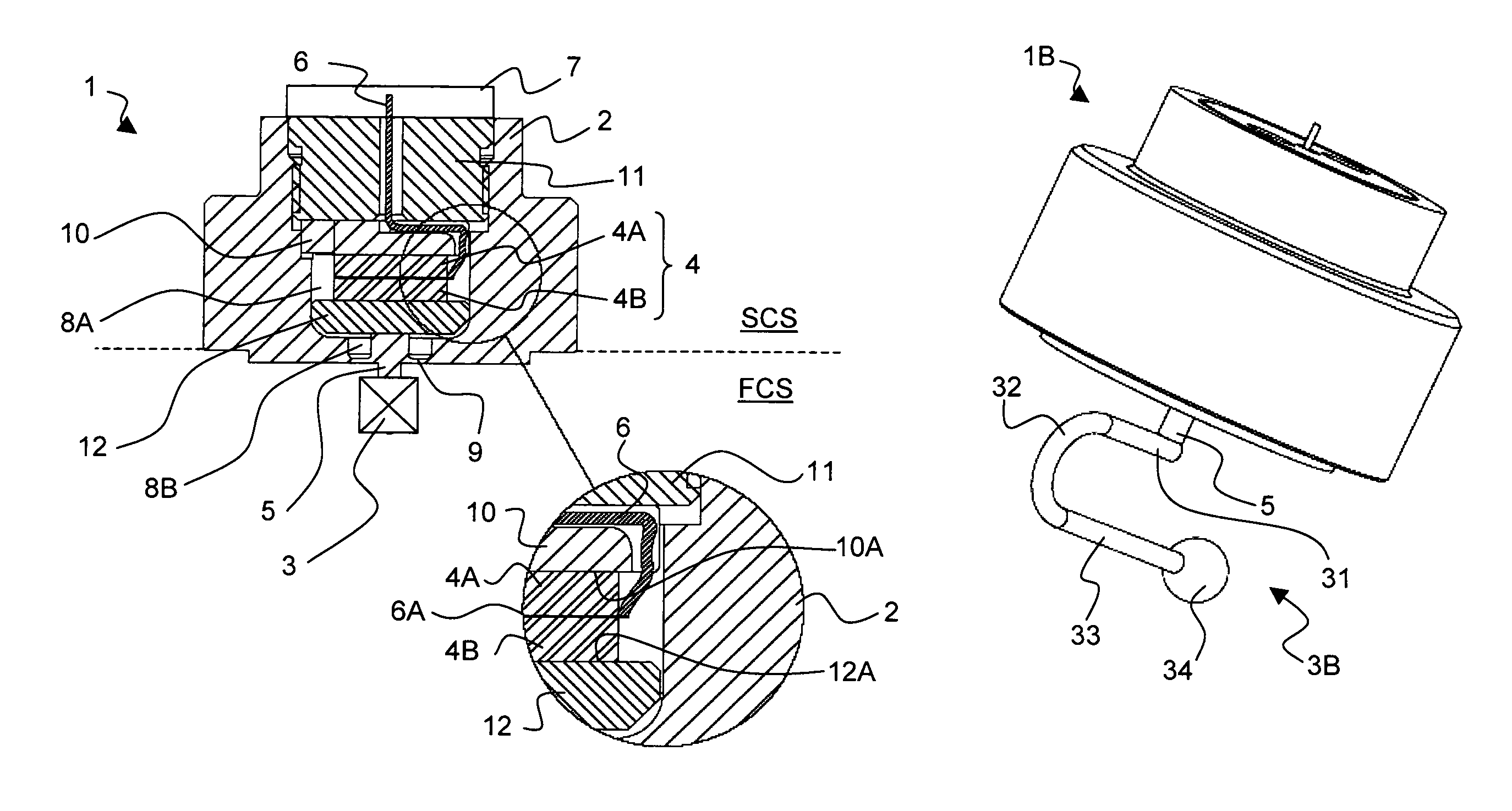
[0078]FIGS. 5, 6 and 7 are side, perspective and bottom views schematically showing a sensor for measuring density and viscosity of a fluid according to a second embodiment 1B of the invention, respectively. In this embodiment, the resonating element 3B is under the form of a non-symmetrical U beam comprising a suspended mass at one end. More precisely, the resonating element 3B comprises a first beam portion 31, a second beam portion 32 bent according to a U, a third beam portion 33. The fir...

fourth embodiment

[0122]An example of a dual mode resonator is described below base on the fourth embodiment shown in FIGS. 11 to 13.

[0123]The resonating element is a paddle shaped beam having an angle with the axe of the excitation movement to allow excitation / detection of vibration modes in the plane of the paddle and perpendicularly to this plane.

[0124]The first resonance mode is characterized by a first resonant frequency F1 and a first quality factor Q1. This mode corresponds to the paddle oscillating perpendicularly to its plane. In this mode, the paddle moves a large volume of fluid. Consequently, the first resonant frequency F1 is highly sensitive to fluid density. The second resonance mode is characterized by a second resonant frequency F2 and a second quality factor Q2. This mode corresponds to the paddle oscillating within its plane. In this mode, the paddle mostly shears the surrounding fluid. Consequently, the second resonant frequency F2 is quite insensitive to fluid density while being...


PUM

PropertyMeasurementUnit
densityaaaaaaaaaa
densityaaaaaaaaaa
temperatureaaaaaaaaaa

Abstract

A density and viscosity sensor for measuring density and viscosity of a fluid, and method for measuring, are presented herein. The sensor comprises a resonating element, and actuating / detecting element, a connector and a housing. The actuating / detecting element is positioned within a chamber defined by the housing so as to be isolated from the fluid. The resonating element is arranged to be immersed in the fluid, and has a shape defining a first resonance mode and a second resonance mode characterized by different resonance frequencies and different quality factors. The first resonance mode is adapted to move a volume of fluid, and the second resonance mode is adapted to shear a surrounding fluid.

Description

FIELD OF THE INVENTION[0001]The invention relates to a sensor for measuring density and viscosity of a fluid. The sensor is based on the use of mechanical elements put into vibration in the fluid to be measured.[0002]The invention is applicable to density and viscosity measurements in the oilfield industry, in the chemical industry, in the food industry, etc. . . .BACKGROUND OF THE INVENTION[0003]The density is a measure of a mediums mass per unit of volume. The SI unit of density is the kilogram per cubic meter (kg / m3). As examples, at standard temperature and pressure condition, the density of water is 1000 kg / m3, of ethyl alcohol is 790 kg / m3, respectively.[0004]Viscosity is a measure of the resistance of a fluid to deformation. Viscosity describes a fluid internal resistance to flow and may be thought of as a measure of fluid friction. The SI physical unit of dynamic viscosity is the Pascal second (Pa·s). The cgs physical unit for dynamic viscosity is the poise (P). It is more c...

Claims


Application Information

Patent Timeline
Patent Type & Authority Patents(United States)
IPC IPC(8): G01N9/10G01N11/16
CPCG01N9/002G01N11/16
Inventor CHAUDOREILLE, FRANCOISPERMUY, ALFREDDONZIER, ERIC
Owner SCHLUMBERGER TECH CORP
Why Eureka
Try Eureka