Flow enhancement for underwater turbine

a technology of ducted turbines and underwater water, which is applied in the direction of motors, sea energy generation, tidal stream/damless hydropower, etc., can solve the problems of high cycle fatigue, excessive deflection, vibration, etc., and achieve optimal bi-directional water flow performance, minimizing turbulent water flow, and greater noise suppression

Inactive Publication Date: 2011-01-25
CLEAN CURRENT PARTNERSHIP
View PDF108 Cites 77 Cited by
  • Summary
  • Abstract
  • Description
  • Claims
  • Application Information

AI Technical Summary

Benefits of technology

[0009]It is an object of the present invention to implement an improved hydro turbine generator and method of flow enhancement wherein the improvement comprises a slot between a duct or housing and an augmentor device which is disposed about the duct. The augmentor device optimally has an inlet and an outlet which are substantially similar in area and a narrower central throat portion, thereby increasing the efficiency of the turbine. Specific optimal ratios of the throat area, slot area and the blade area to the inlet area are disclosed which further optimize the efficiency of the turbine.
[0011]Another object of the present invention is to provide an augmentor which is axi-symmetric, with leading edges having hydrodynamic profiles, thereby minimizing turbulent water flow past the inlet and outlet and performing optimally in bi-directional water flow. The dual duct structure may be coated with an anti-fouling coating and may include buoyancy material, thereby achieving greater noise suppression, ensuring minimal environmental impact and providing corrosion resistance and high lubricity.
[0012]Another object of the present invention is to provide a flow enhancement structure in a turbine comprising a longitudinal hole substantially along the longitudinal axis of the turbine in a hub having specific shape, structural and material characteristics, thereby improving the efficiency of the turbine. Specific ratios of the hole area to the blade area are disclosed. The hole, combined with the flow characteristics of the hub, renders the turbine safe in relation to marine life.

Problems solved by technology

However, this system is mechanically complicated.
U.S. Pat. No. 2,509,442 to Matheisel disclosed a ducted propeller turbine with no hub or root section to the blade which is prone to excessive deflection, vibration and high cycle fatigue, particularly as without an inner support ring the blades are cantilevered towards the centre of the unit from the housing.
The Williams patents do not incorporate a set of bearings at the hub to improve the structural integrity of the unit and reduce blade deflection.

Method used


Image

  • Flow enhancement for underwater turbine
  • Flow enhancement for underwater turbine
  • Flow enhancement for underwater turbine

Examples


Embodiment Construction

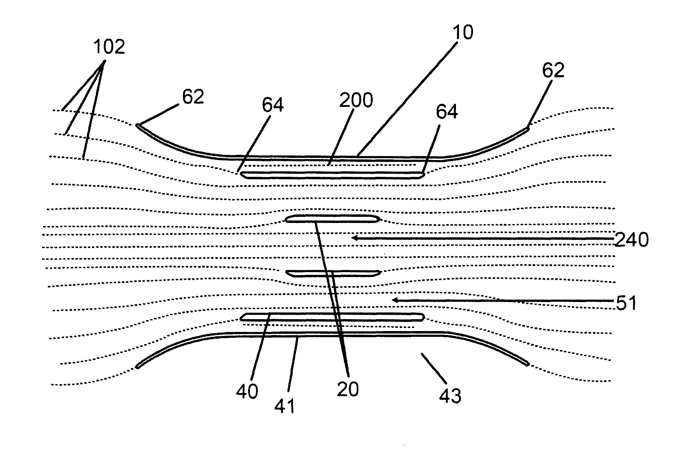
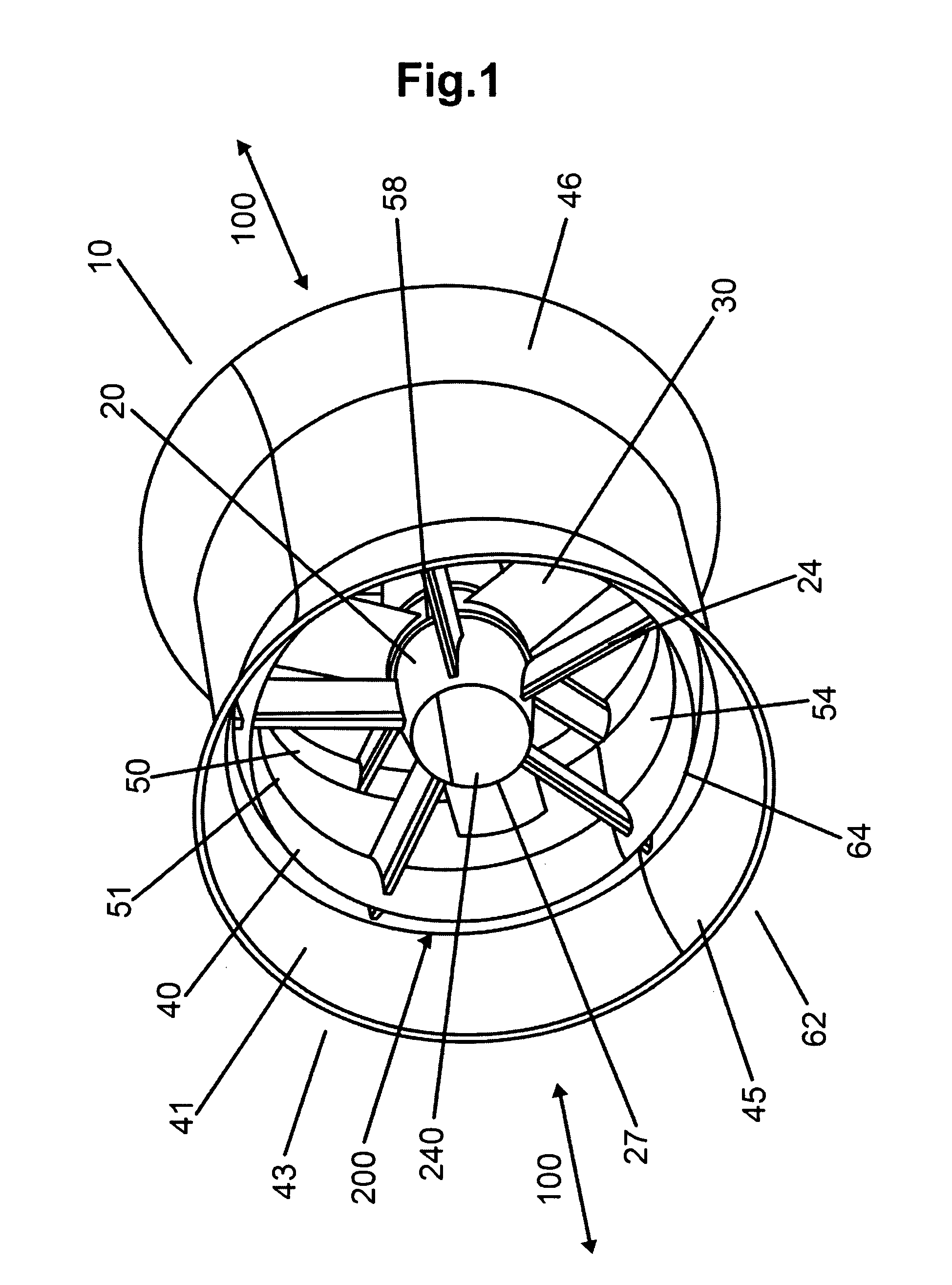
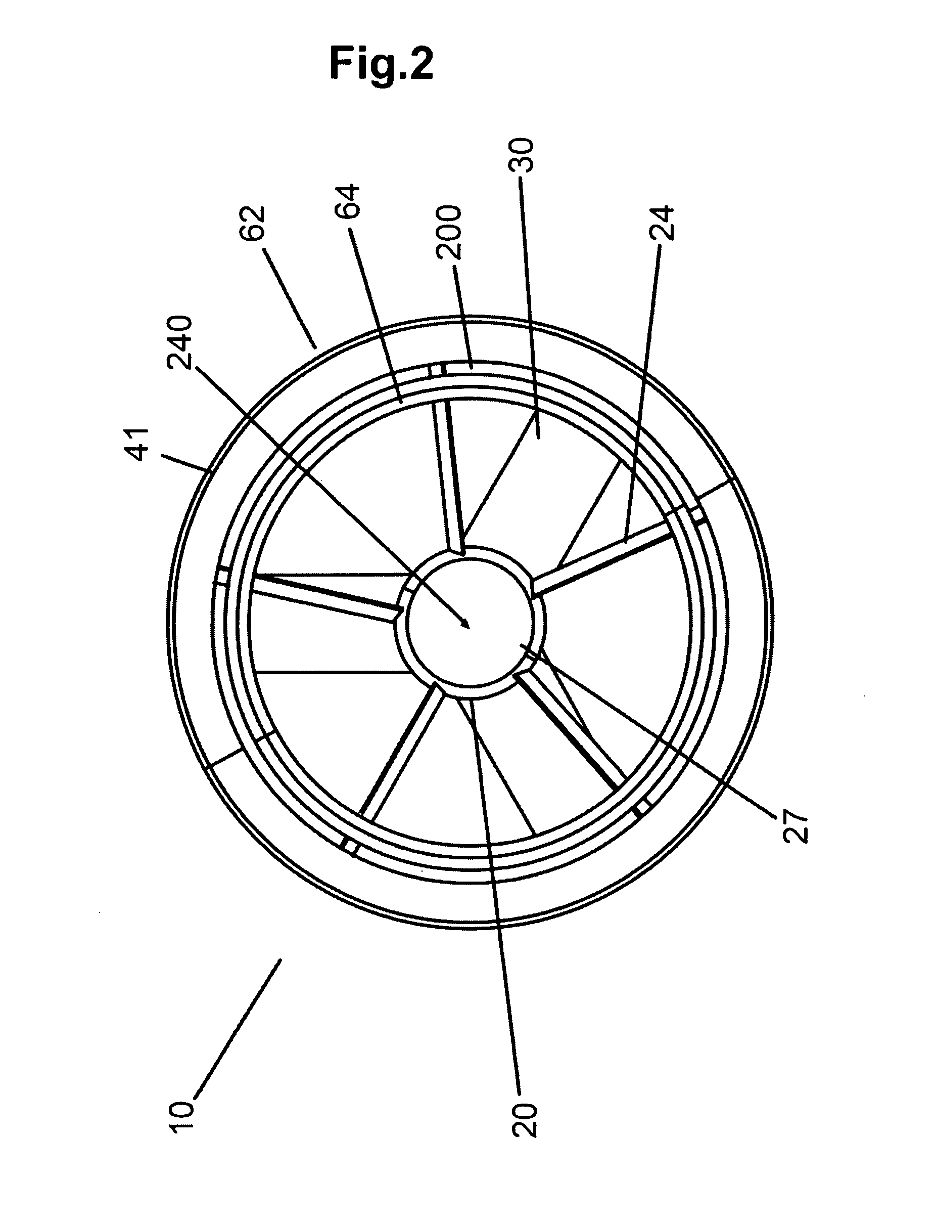
[0021]Referring to FIG. 1, an isometric view of the dual augmentor duct underwater turbine generator 10 with slot 200 and hollow hub 240 flow enhancement structures of the preferred embodiment is shown. In the preferred embodiment, the underwater ducted turbine 10 is of the type disclosed in the applicants' earlier invention the subject of PCT / CA02 / 01413 application to Davis et al., with the present improvement being directed towards a hollow hub 20 design and second, augmentor duct 41 disposed about the outer duct 40 with a slot 200 between the two ducts 43, which together enhance water flow 100 and increase efficiency of the turbine generator 10. The dual augmentor duct structure 43 is a fore and aft symmetric structure, namely it is symmetrical about a central vertical plane which transects the turbine generator 10 laterally. The dual duct structure 43 is disposed about the turbine rotor 50 and all generator components which are housed in the outer duct 40. The augmentor duct 41 ...


PUM


Abstract

A flow enhancement improvement for an underwater turbine generator (10) is disclosed wherein a longitudinal hole (240) is disposed in the central area (26), typically a hub (20) of the generator (10), and a second, augmentor duct (41), preferably rigid, is disposed about the outer duct (40) or housing of the unit to create a slot (200) area. The slot (200) and hollow hub (20) create areas of smooth, laminar fluid flow. The leading edges of the hub (20) or central ring and the augmentor (41) and outer ducts (40) are elliptical to enhance the fluid dynamics of the structure.

Description

1. TECHNICAL FIELD[0001]The present invention relates generally to underwater ducted turbines for hydrokinetic electrical power generation. More specifically, a dual augmentor duct structure defining a slot and a longitudinal hole through the hub of the turbine which enhances water flow are disclosed.2. BACKGROUND OF THE INVENTION[0002]Bi-directional, rim generating, ducted underwater turbines for generating electrical power are known, such as the applicant's PCT application PCT / CA02 / 01413 to Davis et al. There is a desire to improve the flow characteristics, and therefore, the efficiency of such designs. Fixed augmentors are known to increase flow through the turbine.[0003]U.S. Pat. No. 4,219,303 to Mouton et al. disclosed a rigid inner primary nozzle within a flexible outer nozzle which slightly overlaps the primary nozzle, creating a space between the nozzles for uni-directional flow.[0004]U.S. Pat. No. 6,406,251 B1 to Vauthier disclosed a system of pivoting flaps on the exterior...

Claims


Application Information

Patent Timeline
Patent Type & Authority Patents(United States)
IPC IPC(8): F03D1/02
CPCF03B3/04F03B3/18F03B17/061F05B2240/12F05B2240/13Y02E10/38F05B2240/97Y02E10/223Y02E10/28Y10S415/908F05B2240/14Y02E10/30Y02E10/20F03B3/12
Inventor STOTHERS, RUSSELLGRILLOS, EMMANUEL
Owner CLEAN CURRENT PARTNERSHIP
Why Eureka
Try Eureka