
Method and system for reducing light pollution

a technology of light pollution and light pollution prevention, applied in the field of systems and methods for reducing light pollution, can solve the problems of affecting the health of people and animals, annoying or wasteful, and affecting the environment, and achieve the effect of preventing light pollution

Active Publication Date: 2011-01-25
TERMA AS
View PDF14 Cites 22 Cited by
  • Summary
  • Abstract
  • Description
  • Claims
  • Application Information

AI Technical Summary

Benefits of technology

This solution effectively reduces light pollution by minimizing the duration of light usage, conserving energy, addressing community concerns about visual impact, and potentially lowering bird fatalities by reducing the duration of light exposure.

Problems solved by technology

Like other forms of pollution (e.g., air pollution, noise pollution, water pollution, soil contamination), light pollution can harm the environment and human and animal health.
Light pollution is a broad term that refers to multiple problems, which are caused by inefficient, annoying or arguably unnecessary use of artificial light.
Often annoying or wasteful light fits several of these categories.
The strong light may cause problems such as sleep deprivation or the blocking of an evening view.
Light is particularly problematic for astronomers.
Stray light may limit an astronomer's ability to observe the night sky.
Indeed, over-illumination (i.e., the excessive use of light) wastes energy equivalent to two million barrels of petroleum per day.

Method used


Image

  • Method and system for reducing light pollution
  • Method and system for reducing light pollution
  • Method and system for reducing light pollution

Examples


Embodiment Construction

[0035]The United States imports vast quantities of oil to satisfy its energy needs. Every megawatt of energy produced by alternative energy sources is one less megawatt that needs to be produced from imported oil, which leads directly to increased energy independence.

[0036]In the United States, 21 states and the District of Columbia currently have Renewable Portfolio Standards (RPSs). RPSs are legislatively mandated requirements that a certain percentage of energy must be produced from renewable sources, such as wind. The specific requirements vary from state to state. The U.S. Congress is currently considering a national RPS.

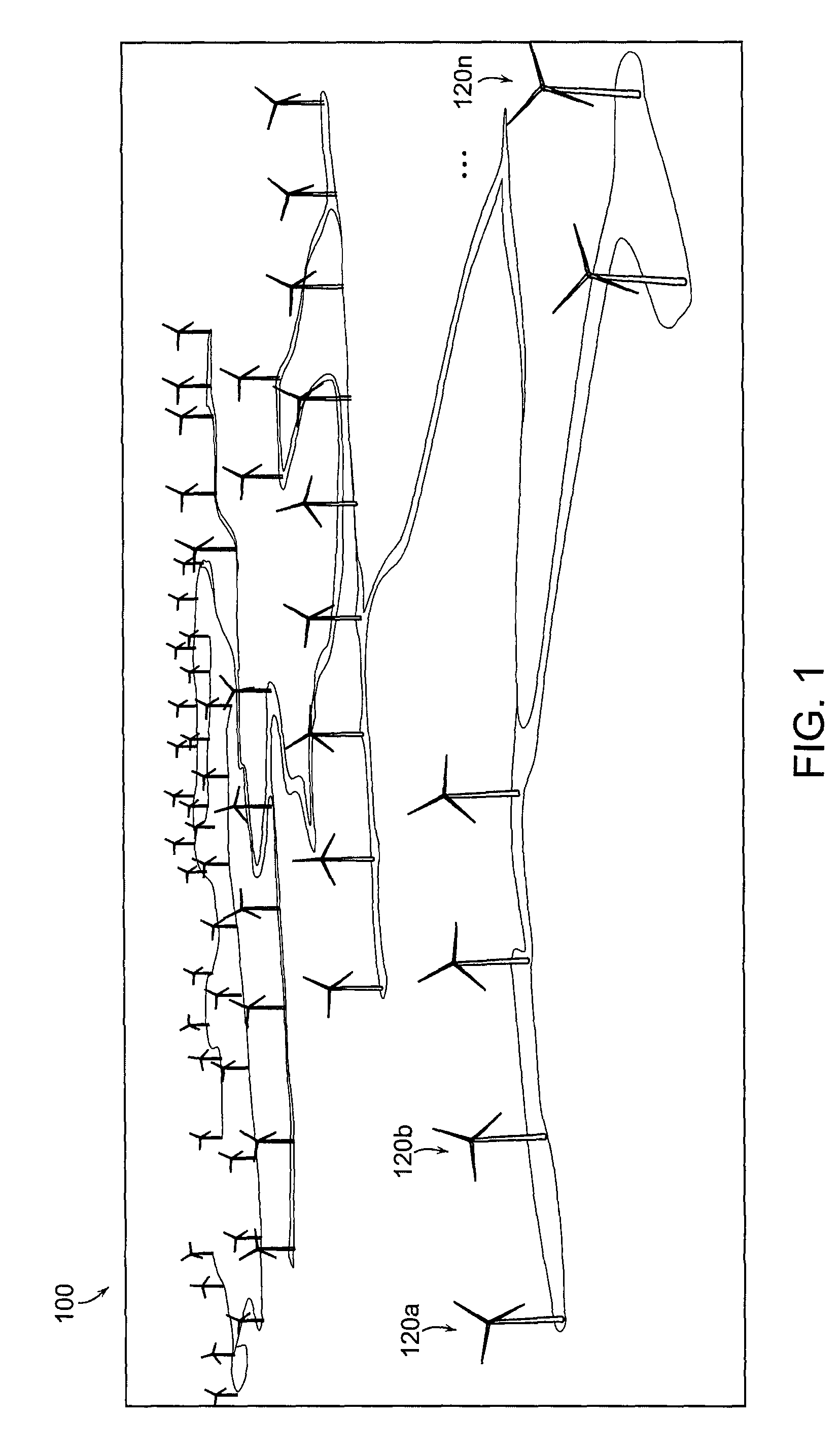
[0037]As shown in FIG. 1, wind power plants or wind farms 100 comprised of wind turbines 120a-120n (generally, 120) are being developed throughout the United States to meet the RPSs. Wind farming is considered to be one of the cleanest methods of producing energy on an industrial scale. A single wind farm can produce hundreds of megawatts of energy without prod...


PUM


Abstract

A system for preventing light pollution includes one or more radar units that monitor for vehicles in a volume surrounding or containing one or more obstructions having one or more obstruction lights. A master radar detection processing unit receives sensed radar detection information from the one or more radar units with associated radar signal processing units and determines whether a vehicle is present within the monitored volume. A plurality of obstruction light controller units are interconnected in a network, such as a wireless network. Each obstruction light controller unit turns on an obstruction light when a vehicle enters the monitored volume or a failure condition exists, and turns off the obstruction light when the vehicle has vacated the monitored volume and no failure condition exists. The one or more radar units can transmit sensed radar detection information to a master radar detection processing unit via the network.

Description

CROSS-REFERENCE TO RELATED APPLICATIONS[0001]This application claims priority to and the benefit of U.S. Provisional Patent Application Ser. No. 60 / 950,223, filed on Jul. 17, 2007, the entire contents of which are incorporated herein by reference.FIELD OF THE INVENTION[0002]In general, the invention relates to systems and methods for reducing light pollution. In particular, the invention relates to systems and methods for controlling warning lights on obstructions, such as wind turbines, to reduce light pollution.BACKGROUND[0003]Light pollution (also known as photo-pollution or luminous pollution) refers to light that is annoying, wasteful or harmful. Like other forms of pollution (e.g., air pollution, noise pollution, water pollution, soil contamination), light pollution can harm the environment and human and animal health.[0004]Light pollution is a broad term that refers to multiple problems, which are caused by inefficient, annoying or arguably unnecessary use of artificial light...

Claims


Application Information

Patent Timeline
Patent Type & Authority Patents(United States)
IPC IPC(8): G01S13/00G08B21/00B64D47/02
CPCF03D11/00F03D11/0041G01S13/87H05B37/02G01S7/003Y02E10/722F03D80/00F03D80/10H05B47/165Y02E10/72
Inventor LAUFER, ERIC DAVID
Owner TERMA AS
Learn More