
Fastener system for fixing hardened plates

a technology of fastener system and hardener, which is applied in the direction of threaded fasteners, screws, washers, etc., can solve the problems of increasing the difficulty of such operations, requiring complex expensive drilling machinery, and exposing certain equipment to wear

Active Publication Date: 2011-02-01
METSO OUTOTEC (FINLAND) OY
View PDF20 Cites 54 Cited by
  • Summary
  • Abstract
  • Description
  • Claims
  • Application Information

AI Technical Summary

Benefits of technology

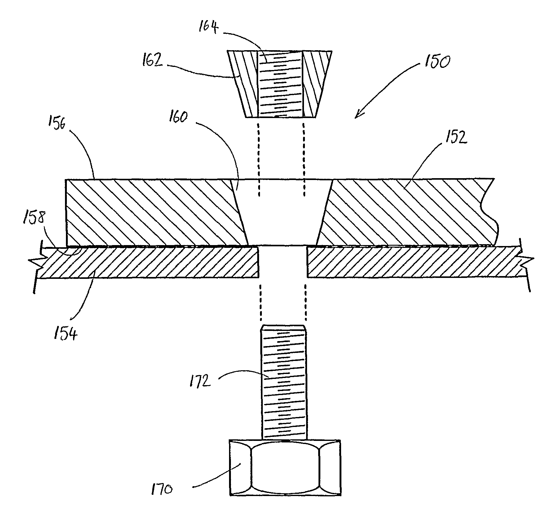
The present invention provides a fastener element with a frusto-conical head and a threaded shaft, where the smallest outer diameter of the frusto-conical head is adjacent the threaded shaft, and the largest outer width of the shaft is smaller than the smallest outer diameter of the head. The frusto-conical head has a half opening angle of 5-20 degrees. The fastener element can be hardened to a Brinell hardness of at least 300 HB. The fastener element can be used in a fastener system with an elongate shaft and a head portion that is engaged with the shaft. The head portion is preferably hardened prior to engagement with the shaft. The hardened plate can be used for fastening to a work piece or for forming a wear plate layer. The frusto-conical hole has a half opening angle of 5-20 degrees. The hardened plate can be used in a system with other plates to form a continuous frusto-conical hole for receiving a complementary fastener element. The hardened plate can be used to minimize the size of the fastener system.

Problems solved by technology

This sort of equipment can be exposed to wear in the form of sliding and / or gouging abrasion.
It is possible to perform cutting, welding, drilling and machining operations on such steels, however the difficulty of such operations increases with the hardness of the material.
For example, when drilling steel of this hardness a tungsten carbide drill bit is usually required, and the feed and speed rates of the drill bit need to be carefully selected, thus requiring complex expensive drilling machinery.
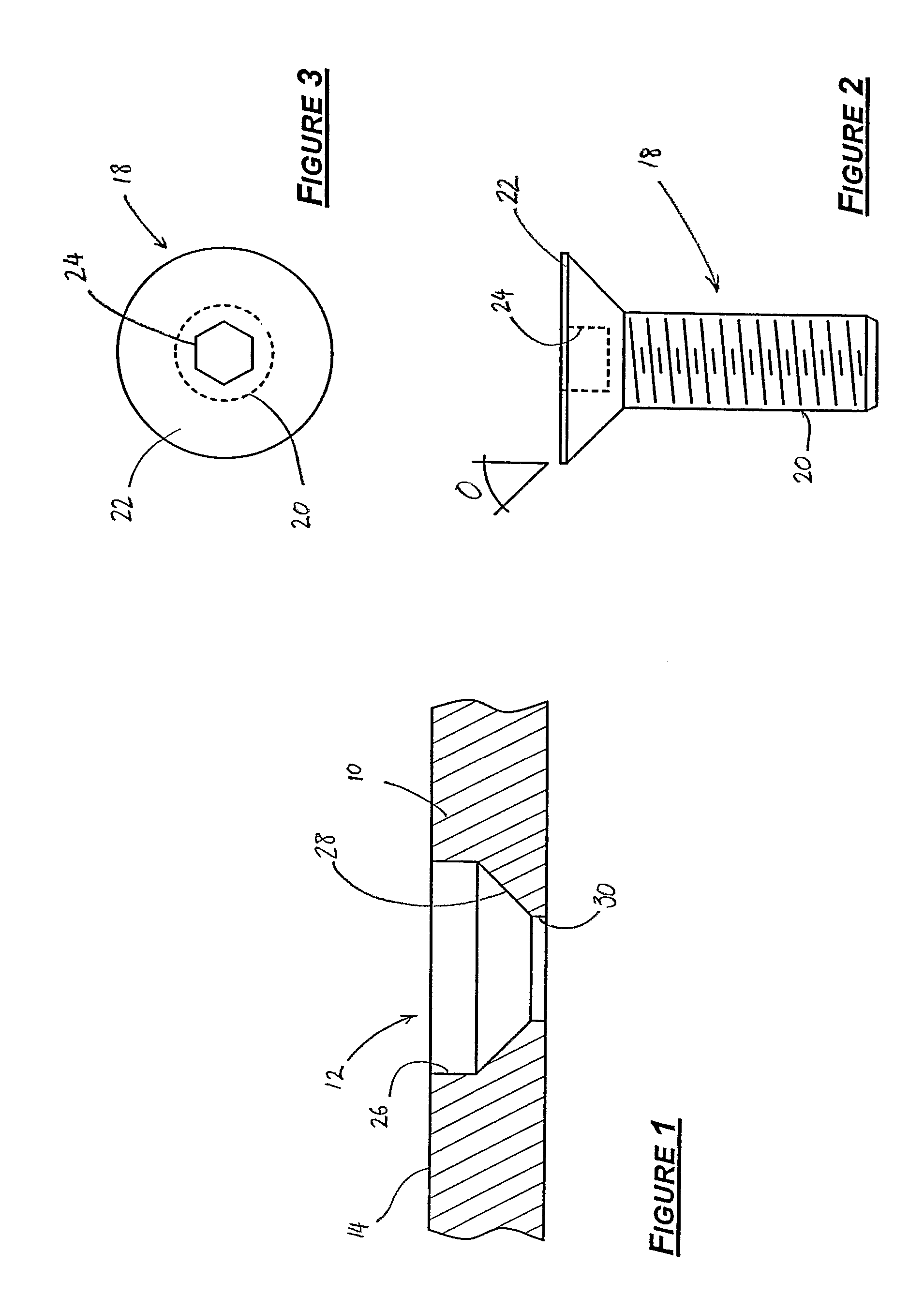
Due to the properties of the material used in the wear plates 10, forming the hole 12 is an expensive and time consuming process.
Given that there can be in excess of 100 wear plates lining, for example, the walls of an ore chute, this is clearly a very time consuming task.
Plant equipment downtime ultimately costs the plant due to lost productivity.

Method used


Image

  • Fastener system for fixing hardened plates
  • Fastener system for fixing hardened plates
  • Fastener system for fixing hardened plates

Examples


Embodiment Construction

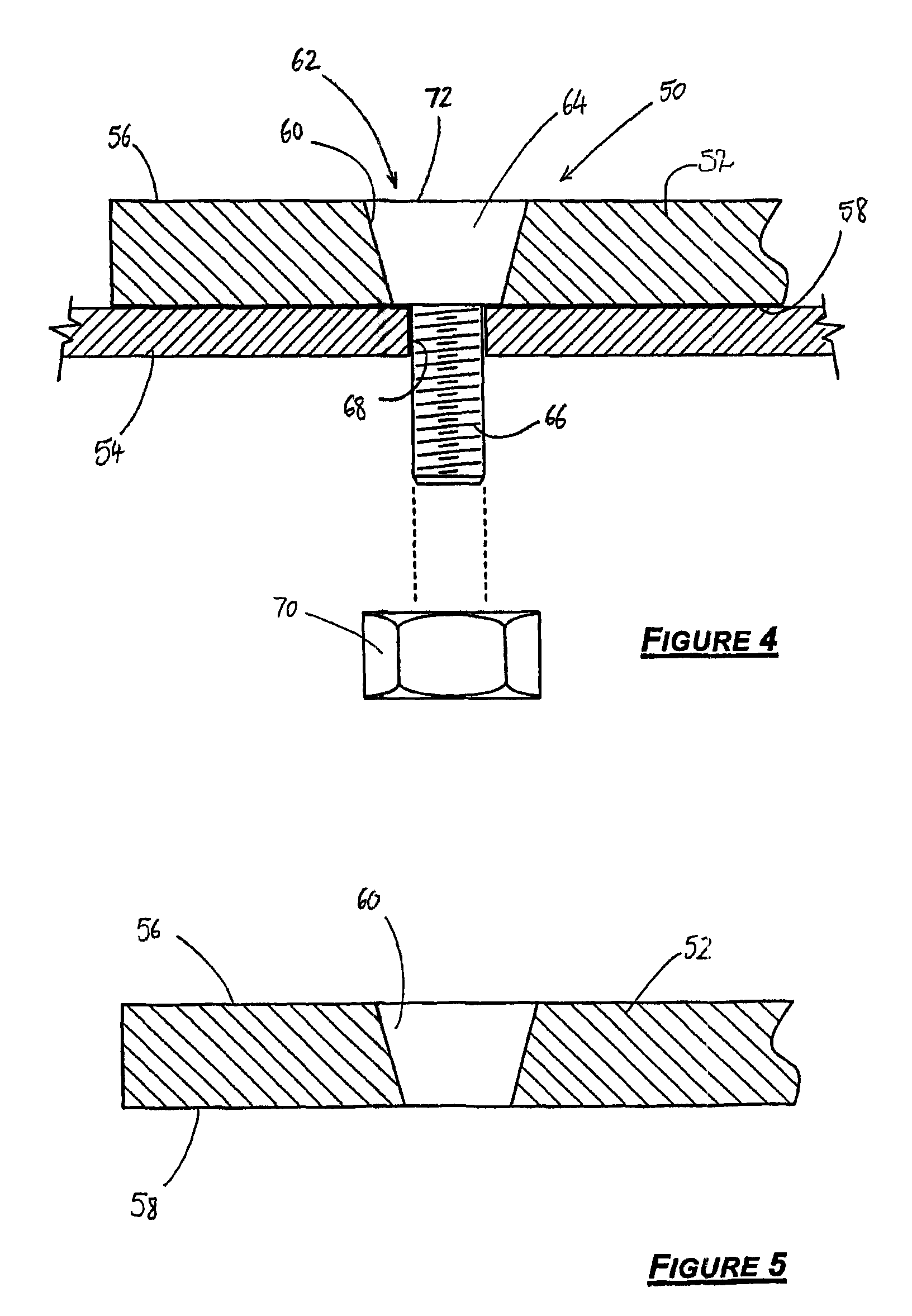
[0137]FIG. 4 shows a schematic cross sectional view of a fixing system 50 according to one embodiment of the present invention. The fixing system 50 fixes a first element, such as a wear plate 52 to a second element, which may be a structural element 54 such as the wall of a hopper or the bin of an earth moving truck or other equipment. The wear plate 52 has a first surface 56 which is exposed to wear, and a second surface 58 which, in use, abuts the structural element 54.

[0138]The wear plate 52 is made of a wear resistant material having a Brinell hardness of at least 300 HB. Typically BISALLOY 500™ or similar is used, which has a typically Brinell hardness of 500 HB.

[0139]A fastener, such as bolt 62, having a head 64 and a threaded shaft 66, is used to secure the wear plate 52 to the structural element 54. The threaded shaft 66 extends through a hole 68 in the structural element 54. A nut 70 is threaded onto the shaft 66 to fix the wear plate 52 to the structural element 54. It wi...


PUM

PropertyMeasurementUnit
Brinell hardnessaaaaaaaaaa
half-opening angleaaaaaaaaaa

Abstract

A fastener system for fixing hardened plates includes a fastener element having a frusto-conical head and a threaded shaft portion, wherein a smallest outer diameter of the frusto-conical head is adjacent the threaded shaft, and a largest outer width of the shaft is smaller than a smallest diameter of the head.

Description

CROSS-REFERENCE TO RELATED APPLICATIONS[0001]This application is a National Phase Application of PCT / AU2005 / 001870, filed Dec. 9, 2005, which claims priority to Australian Patent Application Nos. 2004907031, filed Dec. 9, 2004; 2004907136, filed Dec. 15, 2004; 2005900181, filed Jan. 18, 2005; 2005900691, filed Feb. 15, 2005; and 2005901399, filed Mar. 22, 2005, all of which are incorporated by reference herein.FIELD OF THE INVENTION[0002]The present invention relates to a fastener system for fixing a hardened plate and for minimising wear on structural elements.BACKGROUND OF THE INVENTION[0003]Plates of hardened material, such as steel and steel alloys, are often used to minimise the effect of wear on structural elements of a piece of equipment. Often, these hardened plates are called wear plates because the material of the plate is selected for its resistance to wear. Wear plates are also known to be made of other materials, such as rubber and ceramics. Examples of equipment which ...

Claims


Application Information

Patent Timeline
Patent Type & Authority Patents(United States)
IPC IPC(8): E04B2/00
CPCB60R13/01B65D90/043B65G11/16F16B5/02F16B35/065F16B37/00F16B5/0225Y10T29/49826F16B11/006F16B43/001
Inventor DAVIES, BRIAN
Owner METSO OUTOTEC (FINLAND) OY
Learn More