
Electrostatic atomizing device and air blower using the same

a technology of atomizing device and air blower, which is applied in the direction of drying, lighting and heating apparatus, furniture, etc., can solve the problems of increased size and cost of air purifier as a whole, abnormal discharge, and increased ozone generation

Inactive Publication Date: 2011-02-08
MATSUSHITA ELECTRIC WORKS LTD
View PDF13 Cites 10 Cited by
  • Summary
  • Abstract
  • Description
  • Claims
  • Application Information

AI Technical Summary

Benefits of technology

"The present invention provides an electrostatic atomizing device that can increase the generation of a fine particulate mist of a liquid (e.g., water) while suppressing abnormal discharge and the generation of ozone. The device includes a high voltage generating circuit, a plurality of atomizing electrodes, a counter electrode, and a liquid transfer means. A resistive element is inserted between each atomizing electrode and the high voltage generating circuit to regulate the interelectrode voltage and stabilize the discharge state for electrostatic atomizing. The atomizing electrodes may have a convex curved surface at their tip to reduce electric field concentration. The resistive element may have a smaller resistance value than other resistive elements to flexibly respond to changes in electrostatic atomizing conditions. The device may also include a tank for storing the liquid and a flexible material for the liquid transfer means to increase design flexibility and stability of the air blower. The air blower may also have a variable resistor for automatic adjustment of the electrostatic atomizing state based on the air blowing condition."

Problems solved by technology

However, this results in an increase in size and cost of the air purifier as a whole.
However, there is another problem such as the occurrence of abnormal discharge or an increase in the generation of ozone.

Method used


Image

  • Electrostatic atomizing device and air blower using the same
  • Electrostatic atomizing device and air blower using the same
  • Electrostatic atomizing device and air blower using the same

Examples


Embodiment Construction

[0027]An electrostatic atomizing device and an air blower using the same device of the present invention are explained below in detail according to exemplary embodiments.

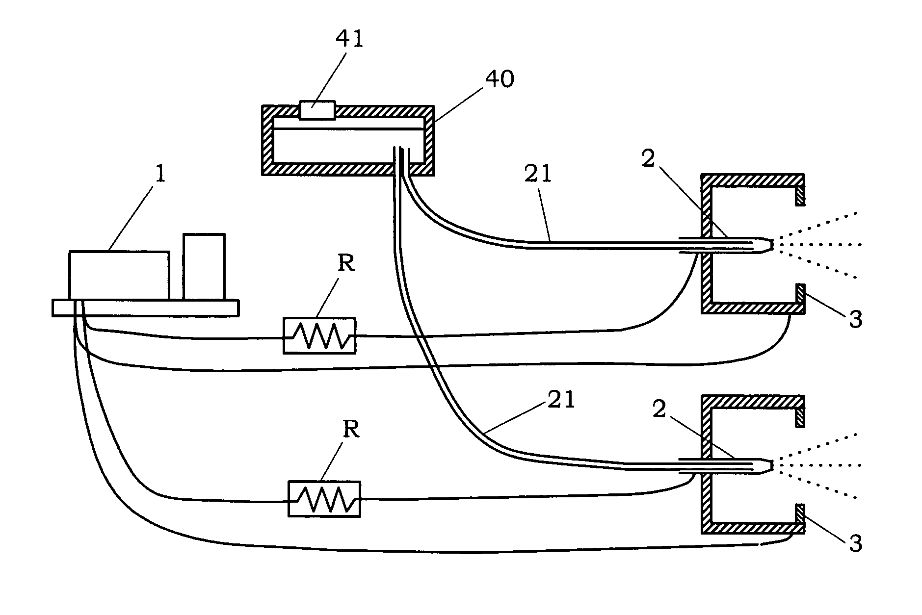
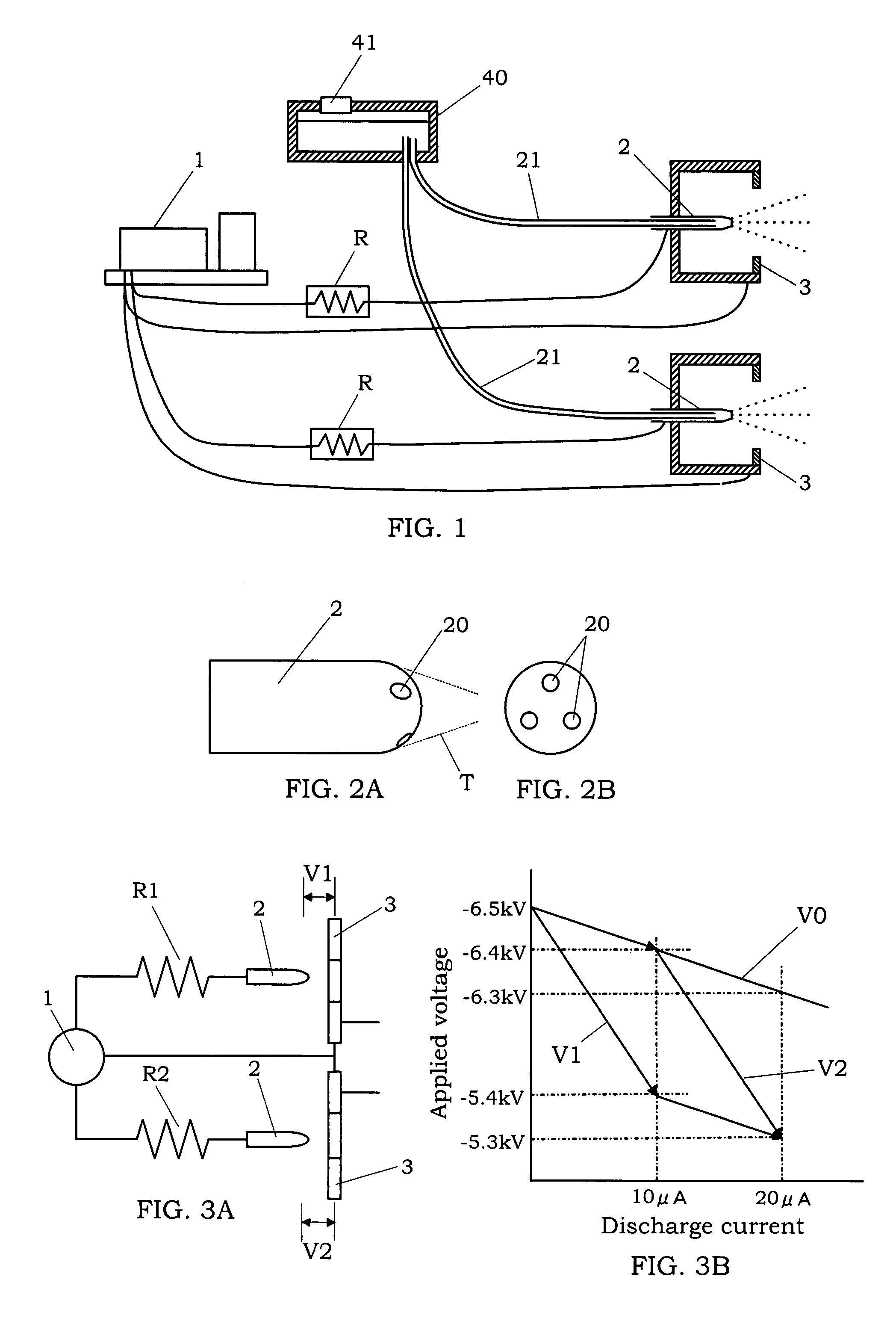
[0028]As shown in FIG. 1, the electrostatic atomizing device of the present embodiment is formed with a high voltage generating circuit 1, a plurality of atomizing electrodes 2 (two atomizing electrodes in the drawing) connected in parallel to the high voltage generating circuit 1, a counter electrode 3 provided at a position facing each atomizing electrode, a tank 40 for storing a liquid such as water, a liquid transfer member 21 for transferring the liquid to each atomizing electrode, and a resistive element R connected between each of the atomizing electrodes 2 and the high voltage generating circuit 1. In the present embodiment, for example, it is possible to use the high voltage generating circuit 1 capable of generating a negative voltage of several kV. In FIG. 1, the numeral 41 designates a liquid compensatin...


PUM


Abstract

An electrostatic atomizing device, which is capable of increasing the generation of a fine mist, while suppressing abnormal discharge and the generation of ozone. This electrostatic atomizing device is equipped with a plurality of atomizing electrodes, to which a high voltage is applied by a single high voltage generating circuit, counter electrodes disposed so as to face the atomizing electrodes; and a liquid transfer means for transferring a liquid (e.g., water) to each of the atomizing electrodes. The atomizing electrodes are connected in parallel to the high voltage generating circuit, and a resistive element for suppressing discharge current is inserted between the high voltage generating circuit and each of the atomizing electrodes.

Description

BACKGROUND OF THE INVENTION[0001]1. Field of the Invention[0002]The present invention relates to an electrostatic atomizing device for atomizing a liquid by use of a high voltage and, more particularly, an electrostatic atomizing device for generating a charged fine particulate mist having a nanometer particle size.[0003]2. Description of the Related Art[0004]As an electrostatic atomizing device capable of atomizing a liquid through the use of Rayleigh fission caused by applying a high voltage to the liquid, for example, there is the one disclosed in Japanese Patent Early Publication No. 5-345156. This electrostatic atomizing device is mainly composed of a tank for storing the liquid, a capillary tube fitted in the tank, and a high voltage generator for applying a high voltage output to the liquid in the tank. The liquid is electrostatically sprayed as a fine particulate mist from a mist outlet provided at the tip of the capillary tube.[0005]By the way, when this kind of electrostat...

Claims


Application Information

Patent Timeline
Patent Type & Authority Patents(United States)
IPC IPC(8): B05B5/00F23D11/32B03C3/00A45D20/12F26B3/34
CPCB05B5/0255B05B5/053B05B5/0533A45D20/12B05B5/08B05B5/035
Inventor MATSUI, YASUNORIOKAWA, KAZUMIISAKA, ATSUSHIMURASE, SHINYAYAMAGUCHI, TOMOHIRO
Owner MATSUSHITA ELECTRIC WORKS LTD
Learn More