Modularized active power filter
a technology of active power filter and module, applied in the direction of power conversion system, ac network circuit arrangement, electrical apparatus, etc., can solve the problems of reducing the service life of the filter, and generating a large amount of harmonic current for the electric power equipment, so as to reduce the manufacturing cost, the time for service is shortened, and the compensation capacity is advanced
- Summary
- Abstract
- Description
- Claims
- Application Information
AI Technical Summary
Benefits of technology
Problems solved by technology
Method used
Image
Examples
first embodiment
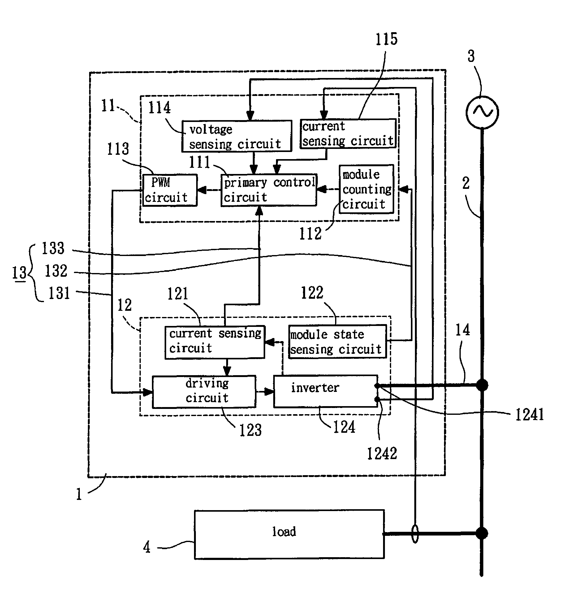
[0018]Referring to FIG. 3, a schematic circuitry of a power system with a modularized active power filter in accordance with the present invention is illustrated. A modularized active power filter 1 electrically connects to a power line 2 between a power source 3 and a load 4 in parallel, with the power source 3 supplying the load 4 with electrical power through the power line 2. The modularized active power filter 1 is employed to provide a compensating current which equals a summation of the fundamental reactive current and the harmonic currents of the load 4. Subsequently, through injecting the compensating current into the power line 2, the harmonic currents of the load 4 is suppressed, and the power factor is improved simultaneously.
[0019]Still referring to FIG. 3, the modularized active power filter 1 comprises a control module 11, a first power module 12, a control signal bus 13, and an AC output line 14. The control module 11 and the first power module 12 electrically connec...
second embodiment
[0027]Still referring to FIG. 4, in operation, in the present invention, the module counting circuit 112 senses the number of the parallel connected power modules is “two” and, then, sends a count result signal to the primary control circuit 111. Therefore, the single module current signal iL-single is calculated with the following equation (2):
[0028]IL2=iL-single(2)
[0029]Then, the primary control circuit 111 obtains the reference signal of the compensating current by the single module current signal iL-single and the detected voltage signal generated by the voltage sensing circuit 114 that senses the voltages of the DC output terminals 1242, 1542.
[0030]Consequently, through the same process of the control module 11 of the first embodiment, the PWM signals are generated by the PWM circuit 113. Then, the PWM signals are passed to the driving circuits 123, 153 of the first and second power modules 12, 15 through the PWM signal lines 131 to obtain the drive signals of the inverters 124...
PUM
 Abstract
Description
Claims
Application Information
 - R&D
- Intellectual Property
- Life Sciences
- Materials
- Tech Scout
- Unparalleled Data Quality
- Higher Quality Content
- 60% Fewer Hallucinations
Browse by: Latest US Patents, China's latest patents, Technical Efficacy Thesaurus, Application Domain, Technology Topic, Popular Technical Reports.
© 2025 PatSnap. All rights reserved.Legal|Privacy policy|Modern Slavery Act Transparency Statement|Sitemap|About US| Contact US: help@patsnap.com


