
Method and apparatus for producing RZ-DPSK modulated optical signals

a modulated optical signal and transmitter technology, applied in electromagnetic transmitters, electromagnetic transmission, multiple carrier systems, etc., can solve the problems of noisy standard nrz drivers, achieve rapid pulse compression or broadening, improve signal integrity, and mitigate pulse distortion

Inactive Publication Date: 2011-02-08
NEPTUNE SUBSEA IP LTD
View PDF11 Cites 7 Cited by
  • Summary
  • Abstract
  • Description
  • Claims
  • Application Information

AI Technical Summary

Benefits of technology

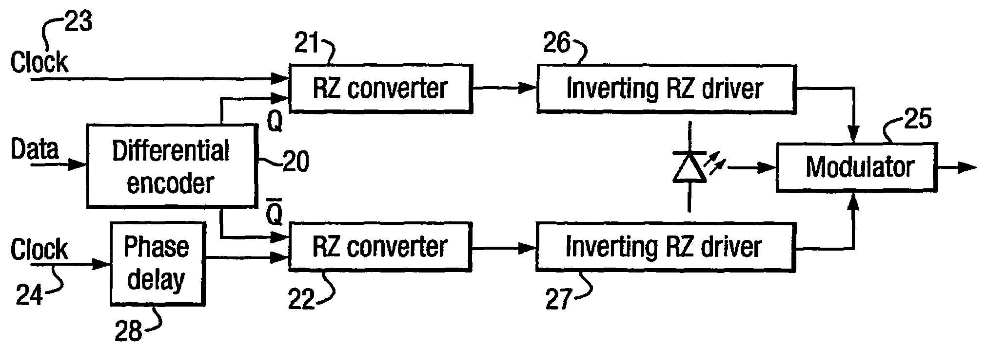
[0012]Preferably, one of the RZ converter outputs can be delayed by adjusting the phase of a clock signal input to the RZ converter, to synchronise the two RZ signals.
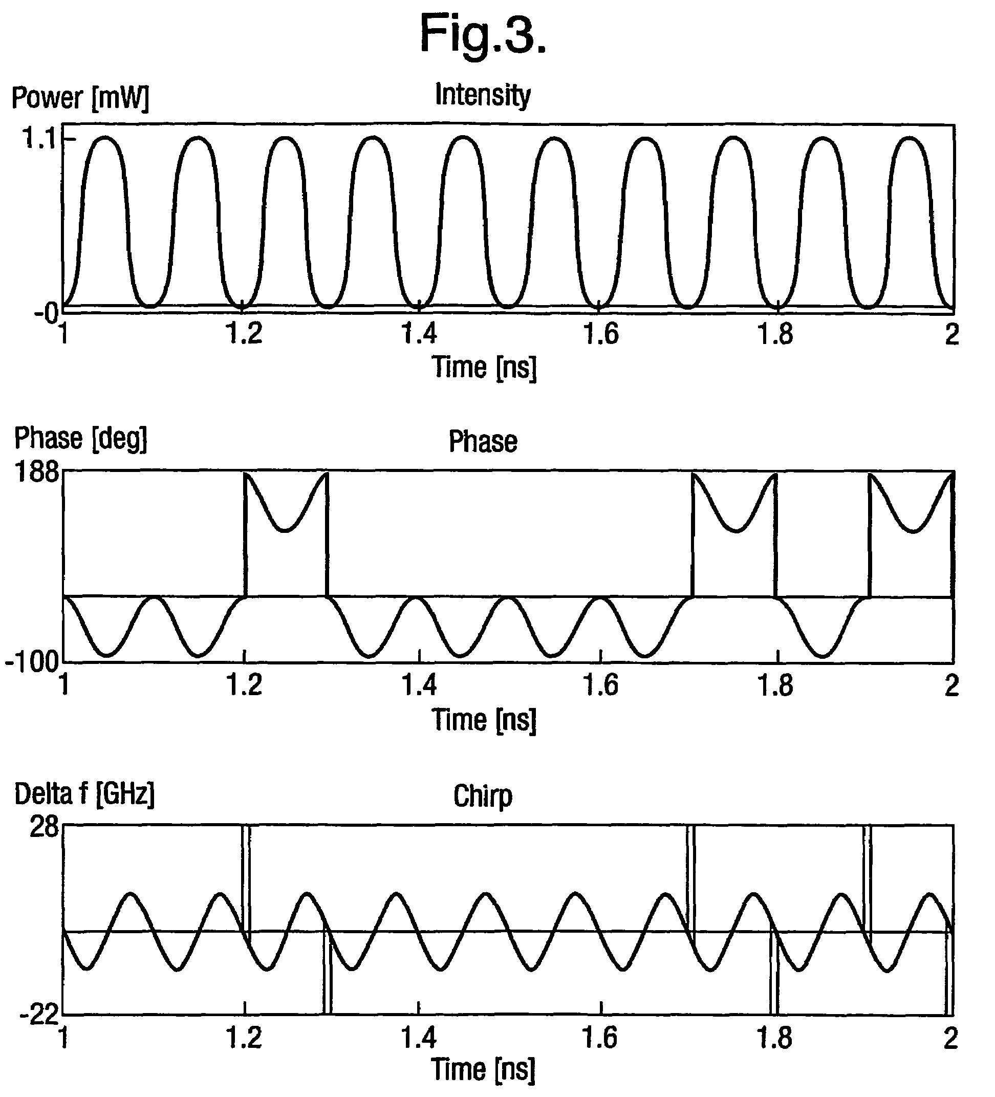
[0018]The present invention provides improved signal integrity as compared with existing RZ-DPSK solutions through the use of high quality RZ drivers. Furthermore, the present invention gives rise to controllable RZ pulse edge chirping, providing rapid pulse compression or broadening through a dispersive fibre length. This typically mitigates pulse distortion in non-linear transmission links.
[0019]The present invention requires the use of only a single Mach Zehnder modulator. All prior RZ-DPSK transmitters require two modulators in series. The present invention accordingly provides benefits in terms of cost, size and power consumption.

Problems solved by technology

Standard NRZ drivers can be particularly noisy due to inter symbol interference (ISI) generated from the broadband driver response.

Method used


Image

  • Method and apparatus for producing RZ-DPSK modulated optical signals
  • Method and apparatus for producing RZ-DPSK modulated optical signals
  • Method and apparatus for producing RZ-DPSK modulated optical signals

Examples


Embodiment Construction

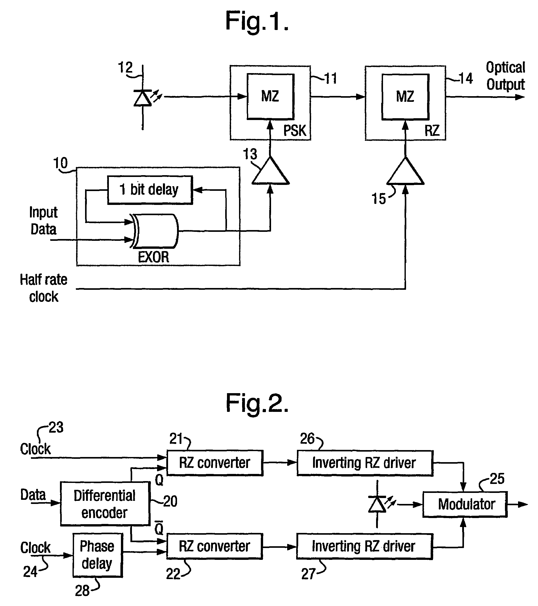
[0025]FIG. 1 shows an RZ-DPSK encoded transmitter in accordance with the prior art. Electrical input data is differentially encoded by differential encoder 10. The differential encoder comprises an exclusive OR gate with the output delayed by one bit and fed back to the input. The differentially encoded data is used to phase modulate a coherent light signal from a coherent light source 12. The modulator shown in FIG. 1 is a Mach Zehnder (MZ) modulator 11, which is chirp-free. The MZ modulator is driven by an NRZ modulator driver 13. The output from the MZ modulator 11 is a phase encoded optical signal. This is converted to an RZ signal by the use of a second MZ modulator 14. The second MZ modulator is used as an RZ pulse carver and is driven by a narrow band modulator driver 15. The driver 15 as shown is driven by a half rate clock at the minima bias point to give a 66% duty cycle.

[0026]The limitations of this type of transmitter are that phase and intensity fluctuations in the opti...


PUM


Abstract

The invention provides an optical transmitter comprising a differential encoder having first and second outputs, the first and second outputs being of opposite polarity to one another, a first RZ converter connected to the first output of the differential encoder and a second RZ converter connected to the second output of the differential encoder, and a dual electrode Mach Zehnder modulator to which an unmodulated coherent light source is coupled, wherein the output of the first RZ converter is connected to a first electrode of the Mach Zehnder modulator and the output of the second RZ converter is connected to a second electrode of the Mach Zehnder modulator. The invention provides improved signal integrity as compared with existing RZ-DPSK solution through the use of high quality RZ drivers. Furthermore, the invention gives rise to controllable RZ pulse edge chirping, providing rapid pulse compression or broadening through a dispersive fibre length. This can be used to mitigate pulse distortion in non-linear transmission links.

Description

FIELD OF THE INVENTION[0001]The present invention relates to a method and transmitter for generating a return to zero differential phase shift keyed (RZ-DPSK) modulated optical signal.BACKGROUND TO THE INVENTION[0002]RZ-DPSK is commonly used in long haul transmission. Typically, a transmitter for generating an RZ-DPSK signal consists of a phase shift keyed (PSK) modulation part and an RZ pulse carving part. In fact, all methods to date require at least two separate modulators in this way, one to phase modulate the signal and one to carve the RZ pulses. This is shown in FIG. 1.[0003]In all methods, the source data must first be differentially encoded, prior to optical modulation. This is typically achieved using a high speed exclusive OR gate with the output tapped and fed back by a one bit delay to the input. This encoding is required because the receiver side demodulator relies on a one bit optical delay for phase comparisons.[0004]To convert the differentially encoded electrical s...

Claims


Application Information

Patent Timeline
Patent Type & Authority Patents(United States)
IPC IPC(8): H04B10/04H04B10/50H04B10/508H04B10/516H04B10/556H04L27/32
CPCH04B10/505H04B10/5051H04B10/5055H04B10/508H04B10/5162H04B10/5561H04L27/32
Inventor OBERLAND, RICHARD
Owner NEPTUNE SUBSEA IP LTD
Learn More