Plasma processing apparatus

a processing apparatus and plasma technology, applied in the field of plasma processing apparatus, can solve the problems of high cost, and achieve the effect of enhancing the insulation between the electrode and the casing and preventing abnormal discharg

Inactive Publication Date: 2011-02-15
SEKISUI CHEM CO LTD
View PDF37 Cites 15 Cited by
  • Summary
  • Abstract
  • Description
  • Claims
  • Application Information

AI Technical Summary

Benefits of technology

[0112]According to the present invention, insulation between the electrode and the casing can be enhanced, abnormal discharge can be prevented from occurring, and the electrode can be adjusted in temperature from outside.

Problems solved by technology

The holder of the apparatus of the above-mentioned Documents is for insulating the electrode from the metal frame, but in order to obtain a reliable insulation, the material and thickness must be carefully selected and thus, the cost becomes high.

Method used


Image

  • Plasma processing apparatus
  • Plasma processing apparatus
  • Plasma processing apparatus

Examples


first embodiment

[0194]the present invention will be described hereinafter with reference to the drawings.

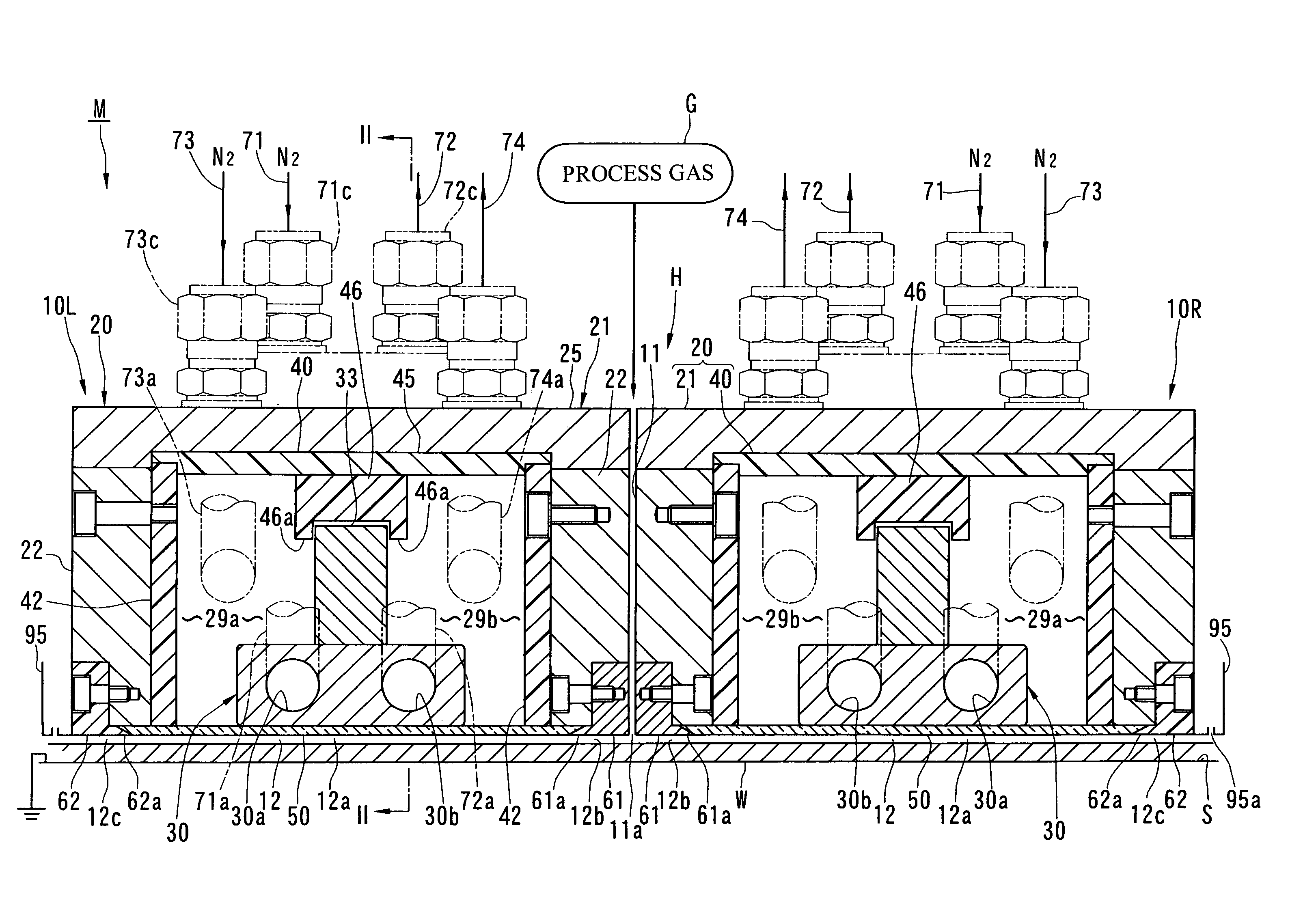
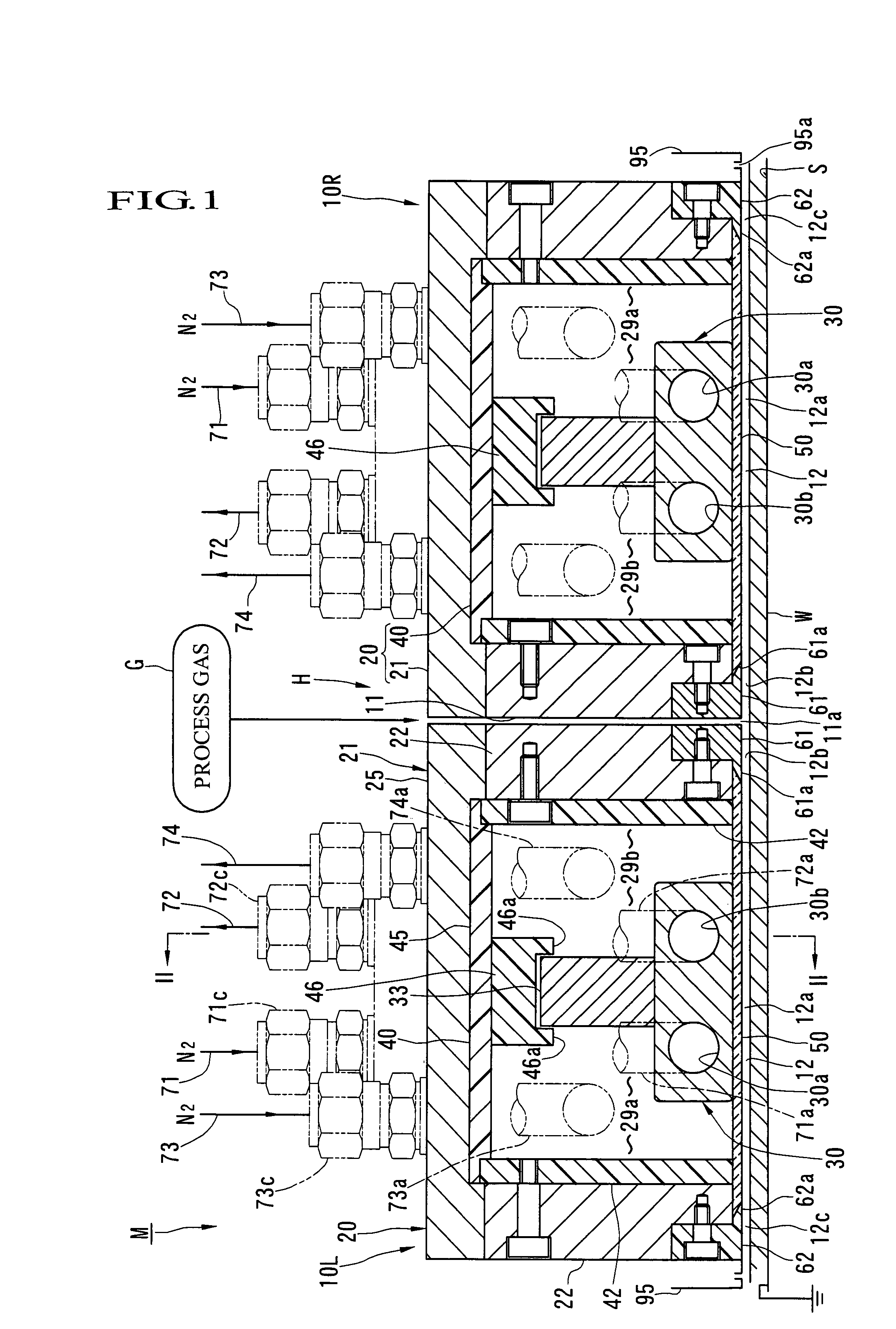
[0195]As shown in FIG. 1, an atmospheric pressure plasma processing apparatus M comprises a processing head H and a stage S. The processing head H is fixed to and supported by an apparatus frame (not shown). The processing head H includes two (plural) left and right processing units 10. A small gap 11 is formed between the two processing units 10. The thickness of the gap 11 is, for example, about 1 mm. A process gas source G is connected to an upper end part of this gap 11. The gap 11 is provided as a process gas introducing passage. A lower end opening 11a of the gap 11 is provided as an introducing port for introducing a process gas to a processing passage 12 as later described. The process gas uses gas species suitable to the contents of processing. For example, in etching processing, a mixing gas or the like is used, which is composed of a fluorine-based gas such as CF4 as a main component ...

second embodiment

[0277]In the second embodiment, the setting is made such that the following expressions are established.

L×Vf / Vs>700×r  (expression 1)

L×Vf / Vs>1400×r  (expression 2)

[0278]wherein r is;

r=(concentration of oxygen in the peripheral air at the gas exhaust port 95a) / (concentration of oxygen in the atmospheric air)  (expression 3)

The concentration of oxygen in the atmospheric air is about 20%. If the flow rate of process gas is represented by Qp; the flow rate of curtain gas, Qc; the flow rate of exhaust gas through the gas exhaust port 95a, Qs and the flow rate of atmospheric air caught, Qa, respectively, the following relation can be established among them.

Qs=Qp+Qc+Qa  (expression 4)

The flow rate Q1 of peripheral air at the gas exhaust port 95a is, as the under-listed expression 5, a sum of the flow rate Qc curtain gas and the flow rate Qa of atmospheric air caught. The flow rate Q1 is equal to a value obtained by subtracting the flow rate Qp of process gas from the entire gas flow rate Q...


PUM

PropertyMeasurementUnit
pressureaaaaaaaaaa
thicknessaaaaaaaaaa
thicknessaaaaaaaaaa

Abstract

To provide a plasma processing apparatus capable of enhancing insulation between an electrode and a casing and adjusting the temperature of the electrode from outside.An electrode 30 is provided at its discharge space forming surface with a solid dielectric 50. The electrode 30 is received in a casing 20 such that the solid dielectric 50 on the discharge space forming surface is exposed. An in-casing space 29 between the casing 20 and the electrode 30 disposed in the casing 20 is filled with substantially pure nitrogen gas. This nitrogen gas pressure is more increased than the pressure in the discharge space. Preferably, nitrogen gas is allowed to flow.

Description

TECHNICAL FIELD[0001]This invention relates to a plasma processing apparatus in which a process gas is introduced into a discharge space and plasma processing is carried out on a substrate.BACKGROUND ART[0002]For example, in a plasma processing apparatus described in Patent Document 1, an electrode connected to a power source and an electrode grounded to the earth are arranged in a vertically opposing relation. Each electrode is received in a metal-made frame through a holder composed of an insulating material such as resin. An atmospheric pressure plasma discharge space is formed between those electrodes and a substrate is arranged in this discharge space so as to be subjected to plasma processing. As a cooling medium for the electrode, water is used in general. The electrodes are firmly fixed to the holder of the apparatus main body without play. Patent Document 2 discloses that electrodes are gently held by a holder.[0003][Patent Document 1] Japanese Patent Application Laid-Open ...

Claims


Application Information

Patent Timeline
Patent Type & Authority Patents(United States)
IPC IPC(8): C23C16/00C23F1/00H01L21/306
CPCH01J37/32348H01J37/32724H05H1/24H01J2237/0206H05H1/2406
Inventor TAKEUCHI, TOSHIMASANAKAJIMA, SETSUOSAITO, NAOMICHINISHIKAWA, OSAMU
Owner SEKISUI CHEM CO LTD
Why Eureka
Try Eureka