Arrangements and methods for facilitating photoluminescence imaging

a technology of photoluminescence and arrangement, applied in the direction of optical radiation measurement, interferometric spectrometry, diagnostics using spectroscopy, etc., can solve the problems of ineffective spectroscopic methods and arrangements implementing the same for decoding the image, and the performance of high-quality fluorescent imaging procedures through a miniature flexible probe may be difficul

Active Publication Date: 2011-02-15
THE GENERAL HOSPITAL CORP
View PDF491 Cites 105 Cited by
  • Summary
  • Abstract
  • Description
  • Claims
  • Application Information

AI Technical Summary

Benefits of technology

[0016]Since exemplary SFE procedures may be conducted using a single optical fiber, images obtained by these exemplary techniques may not contain pixilation artifacts that are commonly observed in fiber bundles. (See E. Laemmel et al., “Fibered confocal fluorescence microscopy (Cell-viZio™) facilitates extended imaging in the field of microcirculation—A comparison with intravital microscopy,” J. Vasc. Res., Vol. 41(5), 400 (2004)). Furthermore, flexibility of the SFE miniature probe will likely be greatly increased, as the bend radius for a single fiber is significantly less than that of imaging bundles. These exemplary advantages of SFE could be of significant benefit for applications where image quality and maneuverability are of concern.
[0018]For example, according to one exemplary embodiment of the present invention, a reference interferometer signal can be used for active feedback control to correct non-linear movement of the scanning mirrors, thereby eliminating the need for post-acquisition processing.

Problems solved by technology

The performance of high quality fluorescent imaging procedures through a miniature flexible probe may be difficult due to the inability to incorporate a rapid beam scanning mechanism at the distal end of miniature probes and the limited number of optical fibers that can fit within the confines of small diameter fiber-optic imaging bundles.
As a result, spectroscopic methods and arrangements implementing the same may not be effective for decoding the image.

Method used


Image

  • Arrangements and methods for facilitating photoluminescence imaging
  • Arrangements and methods for facilitating photoluminescence imaging
  • Arrangements and methods for facilitating photoluminescence imaging

Examples


Embodiment Construction

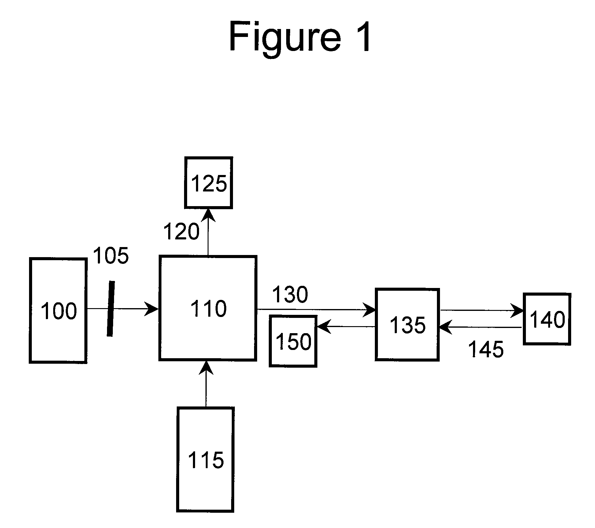
[0048]FIG. 1 shows a schematic diagram of -portions of a spectrally and frequency encoded (“SFE”) system. For example, light 100 can be filtered by filter 105 to match the absorption band of the fluorophore, and provided into an interferometer 110, which can be a Michelson interferometer, as well as a Sagnac, Mach-Zehnder, Twyman-Green interferometers, etc. The input light is affected by the interferometer 110 so as to produce a spectral modulation on the input light. Light 130 from the interferometer 110 then can illuminate a dispersive element 135 which can precede or follow a lens. Each wavelength component with its unique modulation frequency can be focused at a distinct location on a fluorescent sample 140. Fluorescence in the sample 140 is excited, a fluorescent light 145 returns through the grating lens pair 135, and can be collected and directed to a detector 150.

[0049]The detected light can be processed via a Fourier transformation or the like to recover a fluorescence inte...


PUM


Abstract

Exemplary systems and methods for obtaining a photoluminescence radiation from at least one portion of a sample can be provided. For example, using the exemplary embodiment, it is possible to receive a first radiation and disperse the first radiation into at least one second radiation and at least one third radiation. The second and third radiations can be provided to different locations of the portion. In addition, it is possible to receive the photoluminescence radiation from the portion based on the second and third radiations.

Description

CROSS-REFERENCE TO RELATED APPLICATION(S)[0001]This application is based upon and claims the benefit of priority from U.S. Patent Application Ser. No. 60 / 727,215, filed Oct. 14, 2005, the entire disclosure of which is incorporated herein by reference.STATEMENT REGARDING FEDERALLY SPONSORED RESEARCH[0002]This invention was made with Government support under Grant No. FA9550-04-1-0079 awarded by U.S. Department of the Air Force and Grant No. AR007098 awarded by the Public Health Services / National Institutes of Health. The Government has certain rights in this invention.FIELD OF THE INVENTION[0003]The present invention generally relates to arrangements and methods for facilitating photoluminescence imaging, and particularly for, e.g., obtaining fluorescence images via endoscopes, catheters, or small-diameter probes.BACKGROUND OF THE INVENTION[0004]In vivo fluorescence macro- and microscopic imaging is increasingly being used for clinical disease diagnosis and small animal research. In ...

Claims


Application Information

Patent Timeline
Patent Type & Authority Patents(United States)
IPC IPC(8): G01B9/02G01J3/30G01J3/45
CPCA61B1/043A61B1/07A61B5/0071A61B5/0075A61B5/0084G01N21/6408G01N21/6456G01N21/6458A61B5/0066A61B5/7257G01N2021/6419G01N2021/6421
Inventor TEARNEY, GUILLERMO J.YELIN, DVIRVAKOC, BENJAMIN J.BOUMA, BRETT EUGENEMOTZ, JASON T.
Owner THE GENERAL HOSPITAL CORP
Why Eureka
Try Eureka