Component for delivering and locking a medical device to a guide wire

a technology of guide wires and medical devices, applied in the direction of guide wires, dilators, surgery, etc., can solve the problems of significant health problems of patients, emboli release into the circulatory system can be extremely dangerous and sometimes fatal to patients, and achieve the effect of reducing the overall profile of the delivery system and minimizing possible trauma

Inactive Publication Date: 2011-02-22
ABBOTT CARDIOVASCULAR
View PDF764 Cites 6 Cited by
  • Summary
  • Abstract
  • Description
  • Claims
  • Application Information

AI Technical Summary

Benefits of technology

[0014]The present invention relates to a locking component for delivering and locking a medical device, such as an embolic filtering assembly used to capture embolic material that may be created and released into a patient's vasculature during a stenting or angioplasty procedure, along a pre-deployed guide wire. The locking component of the present invention can be used in conjunction with conventional, readily available guide wires or specially-designed guide wires which facilitate the locking features of the present invention. The locking component of the present invention is designed to slide over an elongate guide wire and lock onto a flexible and resilient body member, for example, a helical coil or a polymeric tubular member disposed on or around a portion of the guide wire. The locking component includes means for temporarily compressing at least a portion of the flexible body member (i.e., the coils) of the guide wire when the locking component is advanced over the flexible body member. The locking component further includes a recess which receives the compressed portion of the flexible body member. When the force which compresses the portion of the coil is removed, the resiliency of the formally compressed coils causes them to spring back to their original size within this recess. Once back to their original size, one or more of the coils now placed in the recess will abut against a shoulder or edge formed in the recess locking the locking component in place on the guide wire.
[0015]In one aspect of the invention, for example, when the flexible body member is a helical coil or other springy component, the coupling of the locking component to the helical coil creates a shock absorbing feature which helps to prevent the transmission of unwanted vibration or forces to the attached medical device. In this fashion, the coupling of the locking component to the coils of the guide wire utilizes the springiness and resiliency of the coils to provide shock-absorbing capabilities.
[0018]The locking component of the present invention allows the physician to use or deploy a medical device, such as a distal embolic filtering device, at any point during an interventional procedure without the need to remove a previously deployed guide wire and re-cross the lesion with an entirely separate distal embolic filtering device. Thus, the present invention allows the physician to initially use a conventional guide wire, which performs like a standard guide wire, while providing the physician the option to implement embolic distal protection at any time during the interventional procedure.
[0019]There are multiple possible configurations for the locking component which can be manufactured in accordance with the present invention. For example, the body member which forms the locking component can be tubular, cylindrical, or bullet shaped, just to mention a few configurations. Generally however, the body member of the locking component should usually have a sleek, low-profile shape to minimize possible trauma to the vessel walls of the patient's vasculature especially when the locking component is placed, for example, on the distal end of an embolic filtering assembly. The size and shape of the locking component also should reduce the overall profile of the delivery system in order to reach tight distal locations in the patient's vasculature.
[0020]In one particular aspect, the present invention provides a separately deliverable filter assembly having an expandable basket (also referred to as a “cage”) and a filter element that can be attached to the distal coil tip of a conventional guide wire. In use, the present invention is designed to capture embolic debris created during the performance of a therapeutic interventional procedure, such as a balloon angioplasty or stenting procedure, or other unwanted particulates entrained in the fluid of a body vessel. The present invention allows the physician to deliver the guide wire with “front-line” capabilities to steer through the tortuous anatomy, while still being able to provide filtering protection in the form of a separately deliverable attachment.
[0023]In one particular embodiment of the present invention, the locking component can be used with a specially-designed guide wire which includes a flexible body member located at a position along the length of the guide wire proximal to the distal end coil of the guide wire. Additionally, another specially designed guide wire which can be used with the present invention includes a coil which is rotatably mounted to the guide wire to allow the locking component and attached medical device to spin somewhat freely relative to the guide wire.

Problems solved by technology

However, there is one common problem which can become associated with all of these non-surgical procedures, namely, the potential release of embolic debris into the bloodstream that can occlude distal vasculature and cause significant health problems to the patient.
Additionally, while complete vaporization of plaque is the intended goal during laser angioplasty, sometimes particles are not fully vaporized and enter the bloodstream.
When any of the above-described procedures are performed in the carotid arteries, the release of emboli into the circulatory system can be extremely dangerous and sometimes fatal to the patient.
Debris carried by the bloodstream to distal vessels of the brain can cause cerebral vessels to occlude, resulting in a stroke, and in some cases, death.
Therefore, although cerebral percutaneous transluminal angioplasty has been performed in the past, the number of procedures performed has been somewhat limited due to the justifiable fear of an embolic stroke occurring should embolic debris enter the bloodstream and block vital downstream blood passages.
However, it is often difficult to control the size of the fragments which are formed, and the potential risk of vessel occlusion still exists, making such a procedure in the carotid arteries a high-risk proposition.
However, as mentioned above, there can be complications associated with such systems if the catheter does not remove all of the embolic material from the bloodstream.
Also, a powerful suction could cause trauma to the patient's vasculature.
While a filter can be effective in capturing embolic material, the filter still needs to be collapsed and removed from the vessel.
During this step, there is a possibility that trapped embolic debris can backflow through the inlet opening of the filter and enter the bloodstream as the filtering system is being collapsed and removed from the patient.
When the expandable filter is permanently attached to the guide wire, the device may have added stiffness and therefore may lose some “front-line” capability, which is the ability to negotiate the often tortuous anatomy through which it is being delivered.
The stiffness of a combined expandable filter and guide wire may possibly prevent the device from reaching the desired target area within the patient's vasculature.
As a result, there is a possibility that the deployed filtering portion of the device could scrape the vessel wall possibly causing trauma.
However, since a physician normally delivers interventional devices along the guide wire after the filter portion has been deployed, some manipulation of the guide wire takes place an it may be difficult to prevent at least some rotation at the proximal end of the guide wire.
However, these filtration devices require the fitting to be placed near the distal end of the guide wire which can possibly affect the ability to steer the guide wire and reach the target area in the patient's vasculature.
As such, the presence of the fitting near the distal end of the guide wire may cause unwanted problems during delivery of the guide wire through the patient's vasculature.

Method used


Image

  • Component for delivering and locking a medical device to a guide wire
  • Component for delivering and locking a medical device to a guide wire
  • Component for delivering and locking a medical device to a guide wire

Examples


Embodiment Construction

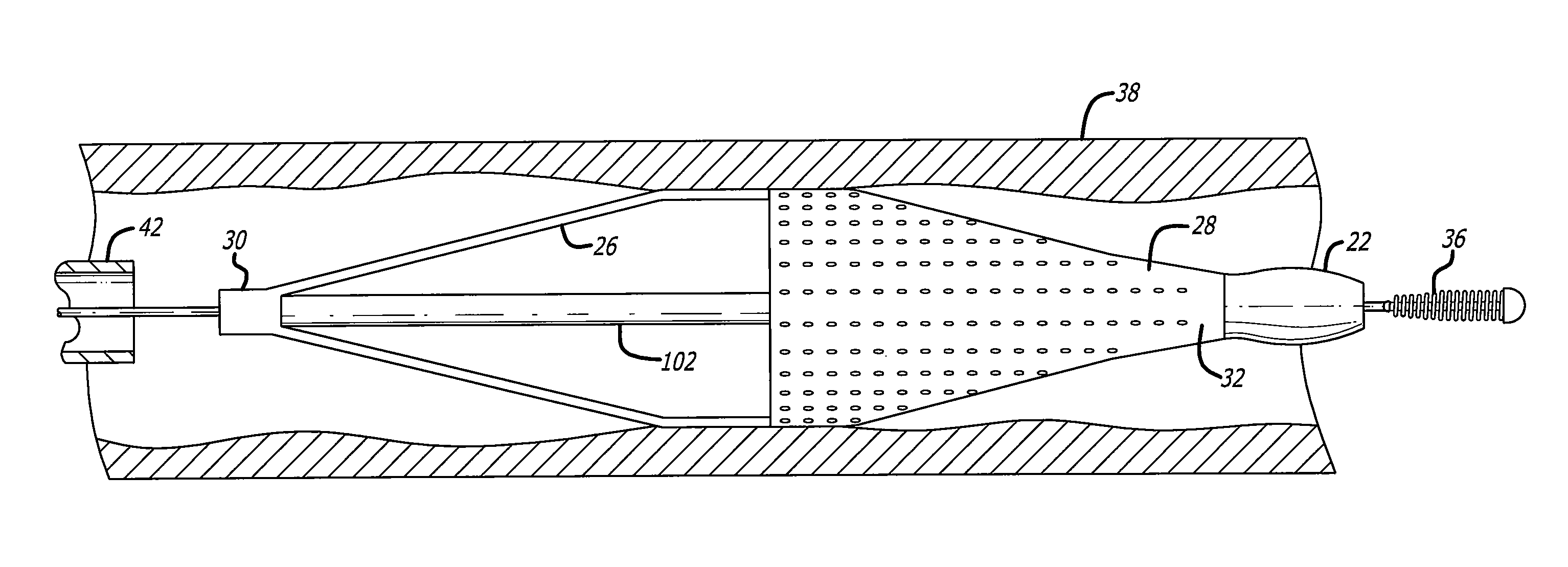
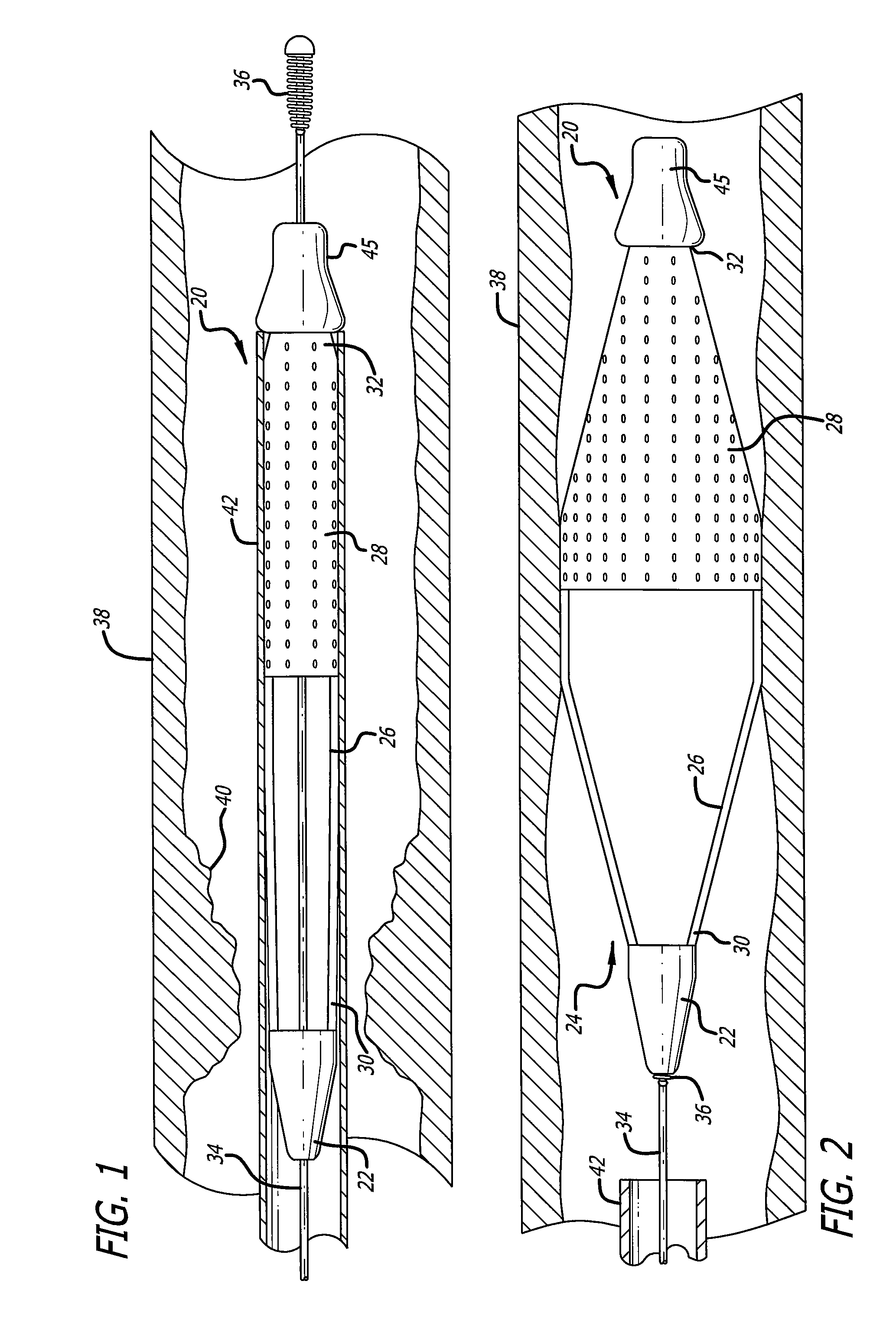
[0039]The present invention relates to a locking component used to deliver and lock a medical device along a pre-deployed guide wire. For the sake of illustration, the following exemplary embodiments are directed to locking components which are attached to embolic filtering devices, although it is understood that the present invention is applicable for use with other medical devices that can be delivered in over-the-wire fashion and locked to a guide wire that has been pre-deployed in a body lumen, such as an artery, vein and other body vessel. By altering the size of the components, the present invention can be suitable for coronary, peripheral and neurological applications. It is to be understood that the present invention is not limited by the embodiments described therein.

[0040]Turning now to the drawings, in which like reference numerals represent like or corresponding elements in the drawings, FIGS. 1 and 2 illustrate one particular embodiment of an embolic filtering device 20...


PUM


Abstract

A locking component delivers and locks an attached medical device along a pre-deployed guide wire. The locking component can lock onto a flexible body member disposed on the guide wire, such as the distal helical tip coil of a conventional guide or a specially-designed guide wire. The locking component includes a tapered opening which temporarily compresses a portion of the helical coil and a locking recess in communication with the tapered opening for receiving the compressed coil. Compressed coils which enter the locking recess will spring back to their original shape (diameter) within the locking recess, locking the component to the coil.

Description

BACKGROUND OF THE INVENTION[0001]The present invention relates generally to medical devices used to perform interventional procedures in a patient's vasculature which can be delivered through the vasculature via a steerable guide wire that has been pre-deployed into an area of treatment, for example, a stenosed or occluded region of an artery or other body vessel. The present invention is more particularly directed to a locking component that can be attached to a medical device, such as embolic filter assembly used to capture embolic material that may be created and released into the vasculature during a stenting or angioplasty procedure, to allow the medical device to be delivered along the guide wire to the target area and locked into place. The locking component of the present invention can be in conjunction with conventional, readily-available guide wires or specially-designed guide wires which facilitate the locking features of the present invention.[0002]Numerous procedures ha...

Claims


Application Information

Patent Timeline
Patent Type & Authority Patents(United States)
IPC IPC(8): A61M29/00
CPCA61M25/09A61M2025/09125
Inventor KELLERMAN, BRADBURKETT, DAVID H.HAYZELDEN, ROBERT
Owner ABBOTT CARDIOVASCULAR
Why Eureka
Try Eureka