
Operational amplifier circuit, bandpass filter circuit, and infrared signal processing circuit

a bandpass filter and infrared technology, applied in electromagnetic transmission, multiple-port active networks, frequency selective two-port networks, etc., can solve the problems of inability to achieve low-voltage operation, inability to improve the power-source noise canceling characteristic by means of the operational amplifier circuit b>103/b>i>a /i>, and the inability to reduce the dynamic range. , the effect of improving the power-source noise canceling characteristi

Active Publication Date: 2011-02-22
SHARP KK
View PDF29 Cites 12 Cited by
  • Summary
  • Abstract
  • Description
  • Claims
  • Application Information

AI Technical Summary

Benefits of technology

The present invention provides operational amplifier circuits, bandpass filter circuits, and infrared signal processing circuits with improved power-source noise cancellation and dynamic range. The operational amplifier circuits have a common-mode feedback circuit that cancels out power-source noise while maintaining the dynamic range. The bandpass filter circuits have a reference voltage that is not affected by the power source voltage, resulting in improved power-source noise cancellation and dynamic range. The infrared signal processing circuits have a common-mode feedback circuit that cancels out power-source noise while maintaining the dynamic range. These improvements are achieved without reducing the dynamic range or sacrificing the power-source noise cancellation characteristic.

Problems solved by technology

However, since the operational amplifier circuit 103a adopting the constant voltage circuit 112 fails to ensure a sufficient dynamic range when operated at a low voltage, the operational amplifier circuit 103a is not suitable for a low-voltage operation.
For the above reasons, improving of a power-source noise canceling characteristic by means of the operational amplifier circuit 103a is not feasible in an infrared remote control receiver.

Method used


Image

  • Operational amplifier circuit, bandpass filter circuit, and infrared signal processing circuit
  • Operational amplifier circuit, bandpass filter circuit, and infrared signal processing circuit
  • Operational amplifier circuit, bandpass filter circuit, and infrared signal processing circuit

Examples


embodiment 1

[0067]The following describes an embodiment of the present embodiment with reference to FIG. 1 to FIG. 3.

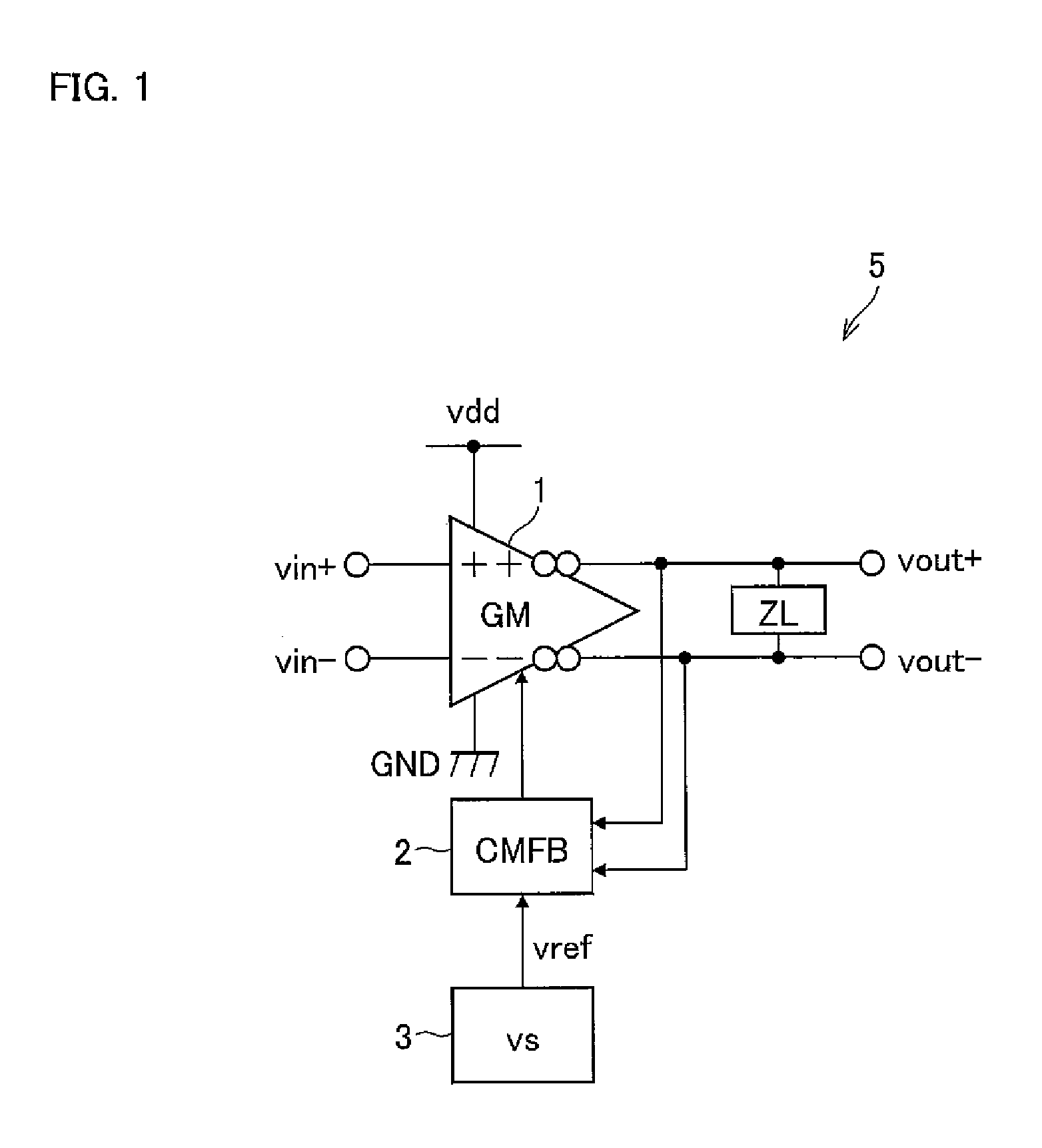
[0068]FIG. 1 shows a configuration of an operational amplifier circuit 5.

[0069]The operational amplifier circuit 5 includes: a transconductance amplifier circuit (hereinafter simply referred to as GM) 1 which converts a differential input voltage into a differential output current; an output load ZL to which a differential output voltage of the GM1 is applied and which constitutes an output terminal of the operational amplifier circuit 5; a common-mode feedback circuit (hereinafter simply referred to as CMFB) 2 to which the differential output voltage of the GM1 and a reference voltage vref are input, and which outputs a control signal to the GM1 so that a D.C. voltage level of the differential output voltage of the GM1 equals the reference voltage vref; and a voltage supply circuit (VS) 3 which supplies the reference voltage vref to the CMFB2. An input terminal of the operationa...

embodiment 2

[0138]An embodiment of the present invention is described below with reference to FIG. 4 to FIG. 7.

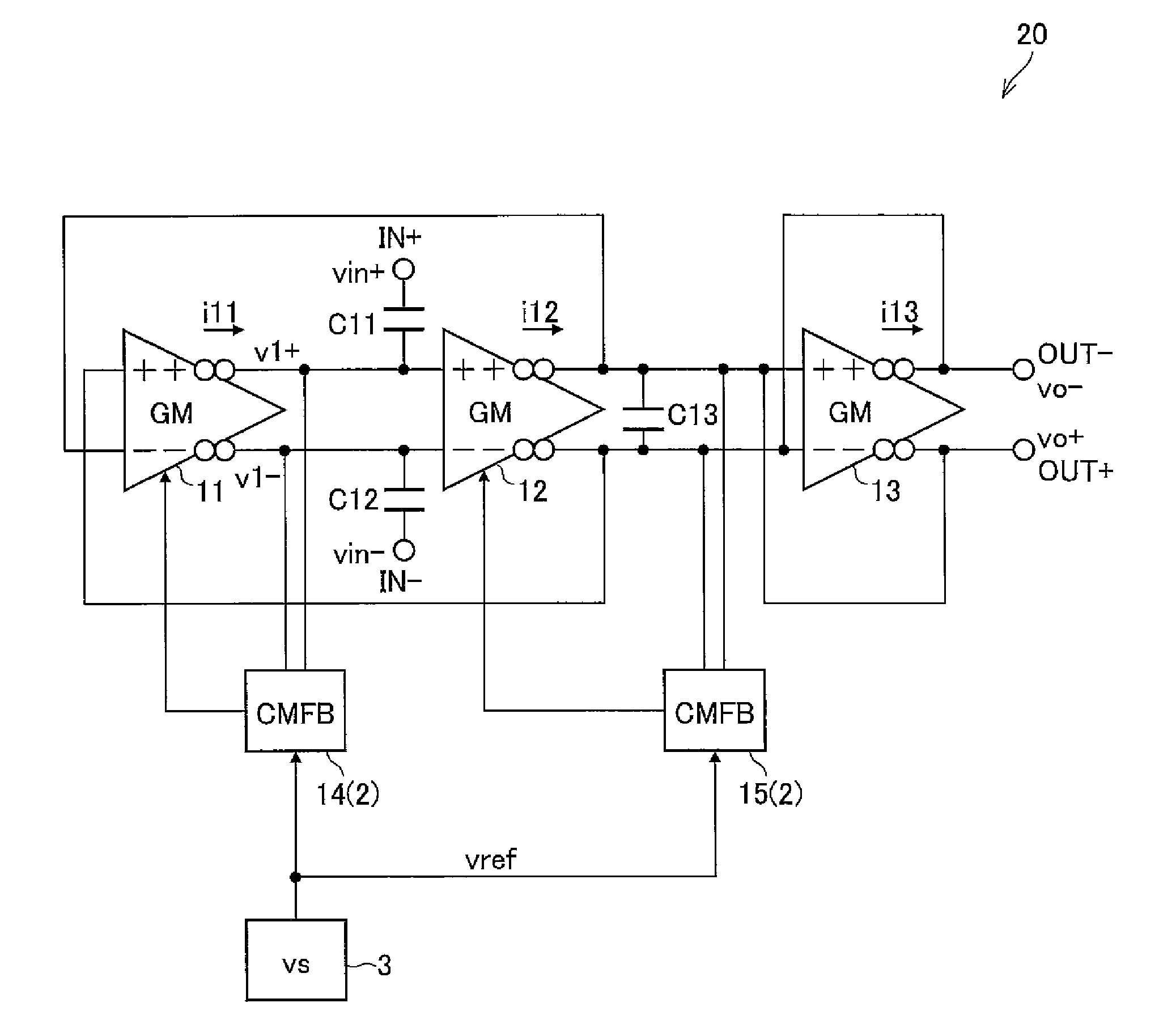
[0139]FIG. 4 shows a configuration of a bandpass filter circuit (hereinafter BPF) 20.

[0140]The BPF 20 is a full-differential bandpass filter circuit including: transconductance amplifier circuits (hereinafter, simply referred to as GMs) 11 to 13 (first to third transconductance amplifier circuits) for converting a differential input voltage into a differential output current; common-mode feedback circuits (hereinafter, simply referred to as CMFBs) 14 and 15 (first and second common-mode feedback circuits); capacitors C11 to C13 (first capacitor to third capacitor); and a voltage supply circuit 3 of the foregoing Embodiment 1. Hereafter, the GM11 to GM13 are sometimes referred to as GM, collectively. Further, no explanation for the voltage supply circuit 3 is provided here, as it is already explained in Embodiment 1.

[0141]A noninverting output section of the GM11 is connected to a nonin...

embodiment 3

[0240]The following describes another embodiment of the present invention with reference to FIG. 8 to FIG. 16.

[0241]The present embodiment deals with an infrared remote control receiver (infrared signal processing circuit) (transmission rate=1 kbps or less, spatial transmission distance=10 m or longer) having a BPF of the present invention. Here, the infrared remote control receiver has functions such as a function to reduce inverter fluorescent light noise, a function to reduce distortion in the waveform of an output from the BPF, or the like.

[0242]As an example of such an infrared remote control receiver, FIG. 8 shows a configuration of an infrared remote control receiver 50a.

[0243]An infrared remote control receiver 50a includes a photodiode chip 31 (photo-acceptance element) and a reception chip 46. The reception chip 46 includes: a current-to-voltage-conversion circuit 32; a capacitor 33; an amplifier (amplifying circuit) 34; the BPF 20b (as an example); a carrier detection ci...


PUM


Abstract

An operational amplifier circuit includes a transconductance amplifier circuit which converts a differential input voltage into a differential output current; a common-mode feedback circuit which outputs a control signal to the transconductance amplifier circuit 1 so as to make a D.C. voltage level of a differential output voltage of the transconductance amplifier circuit equal to a reference voltage; a voltage supply circuit which supplies a reference voltage to the common-mode feedback circuit; and an output load to which the differential output voltage of transconductance amplifier circuit is applied, and which constitutes an output terminal of the operational amplifier circuit 5. A power source voltage is supplied to each of the circuits. The operational amplifier circuit has an improved power-source noise canceling characteristic while maintaining its dynamic range.

Description

[0001]This Nonprovisional application claims priority under 35 U.S.C. §119(a) on Patent Application No. 2006 / 309631 filed in Japan on Nov. 15, 2006, the entire contents of which are hereby incorporated by reference.FIELD OF THE INVENTION[0002]The present invention relates to an operational amplifier circuit, a bandpass filter circuit, and an infrared signal processing circuit whose respective power-source noise canceling characteristics are improved while their dynamic ranges are kept from decreasing.BACKGROUND OF THE INVENTION[0003]Typical examples of an infrared signal processing circuit are: remote controllers of home electric appliances and peripheral devices of personal computers, each of which performs data communication in compliance with IrDA (Infrared Data Association) standard or IrDA Control standard.[0004]For example, a conventional infrared remote control receiver 110 includes a photodiode chip 101 and a reception chip 108 as shown in FIG. 23. The photodiode chip 101 co...

Claims


Application Information

Patent Timeline
Patent Type & Authority Patents(United States)
IPC IPC(8): H04B10/06H03F3/45H03H11/04H03H11/12
CPCH03F3/087H03F3/45192H03F3/45475H03F3/45632H03F3/45928H03F2203/45088H03F2203/45101H03F2203/45134H03F2203/45138H03F2203/45302
Inventor INOUE, TAKAHIRO
Owner SHARP KK
Learn More