Temperature setting method of thermal processing plate, computer-readable recording medium recording program thereon, and temperature setting apparatus for thermal processing plate

a technology of temperature setting apparatus and thermal processing plate, which is applied in the direction of lighting and heating apparatus, furniture, instruments, etc., can solve the problems of long time for temperature setting operation, difficulty in judging whether or not, and variation of line width of wafers among operators, so as to achieve the effect of short tim

Active Publication Date: 2011-03-01
TOKYO ELECTRON LTD
View PDF10 Cites 10 Cited by
  • Summary
  • Abstract
  • Description
  • Claims
  • Application Information

AI Technical Summary

Benefits of technology

[0010]The present invention has been developed in consideration of the above points, and its object is, in the temperature setting of a thermal processing plate such as a thermal plate, to accurately estimate processing states of a substrate such as a wafer after change of the temperature settings and perform the temperature setting of the thermal processing plate in a short time and properly.
[0013]According to the present invention, an improvement component improved by change of the temperature setting of the thermal processing plate of the current processing stated of the substrate is obtained using a predetermined expression, and the improvement component is subtracted from the current processing states of the substrate to calculate the processing states of the substrate after change of the temperature setting. Therefore, the processing states of the substrate after change of the temperature setting can be accurately estimated irrespective of, for example, the level of skill of an operator. As a result, it is unnecessary to repeat the change of the temperature setting through a try and error process, so that the temperature setting of the thermal processing plate can be performed in a short time and properly.
[0020]According to the present invention, the processing states of the substrate after change of the temperature settings of a thermal processing plate can be accurately estimated, so that the temperature setting of the thermal processing plate can be performed in a short time and properly.

Problems solved by technology

However, it is difficult to judge whether or not the line width by the temperature setting at that point in time is appropriate halfway through the temperature setting operation in the above-described temperature setting since a line width to be finally reached is not correctly known, and therefore the operator usually ends the temperature setting operation at the point in time when the operator judges that the line width has become appropriate by his / her subjectivity.
As a result, an optimal temperature setting may not have been made, thus causing variations, among operators, in line widths within the wafer after the temperature setting.
Further, if a finally optimal line width is not known, the operator sometimes performs change of the temperature setting a number of times through a try and error process, thus taking a long time for the temperature setting operation.

Method used


Image

  • Temperature setting method of thermal processing plate, computer-readable recording medium recording program thereon, and temperature setting apparatus for thermal processing plate
  • Temperature setting method of thermal processing plate, computer-readable recording medium recording program thereon, and temperature setting apparatus for thermal processing plate
  • Temperature setting method of thermal processing plate, computer-readable recording medium recording program thereon, and temperature setting apparatus for thermal processing plate

Examples


Embodiment Construction

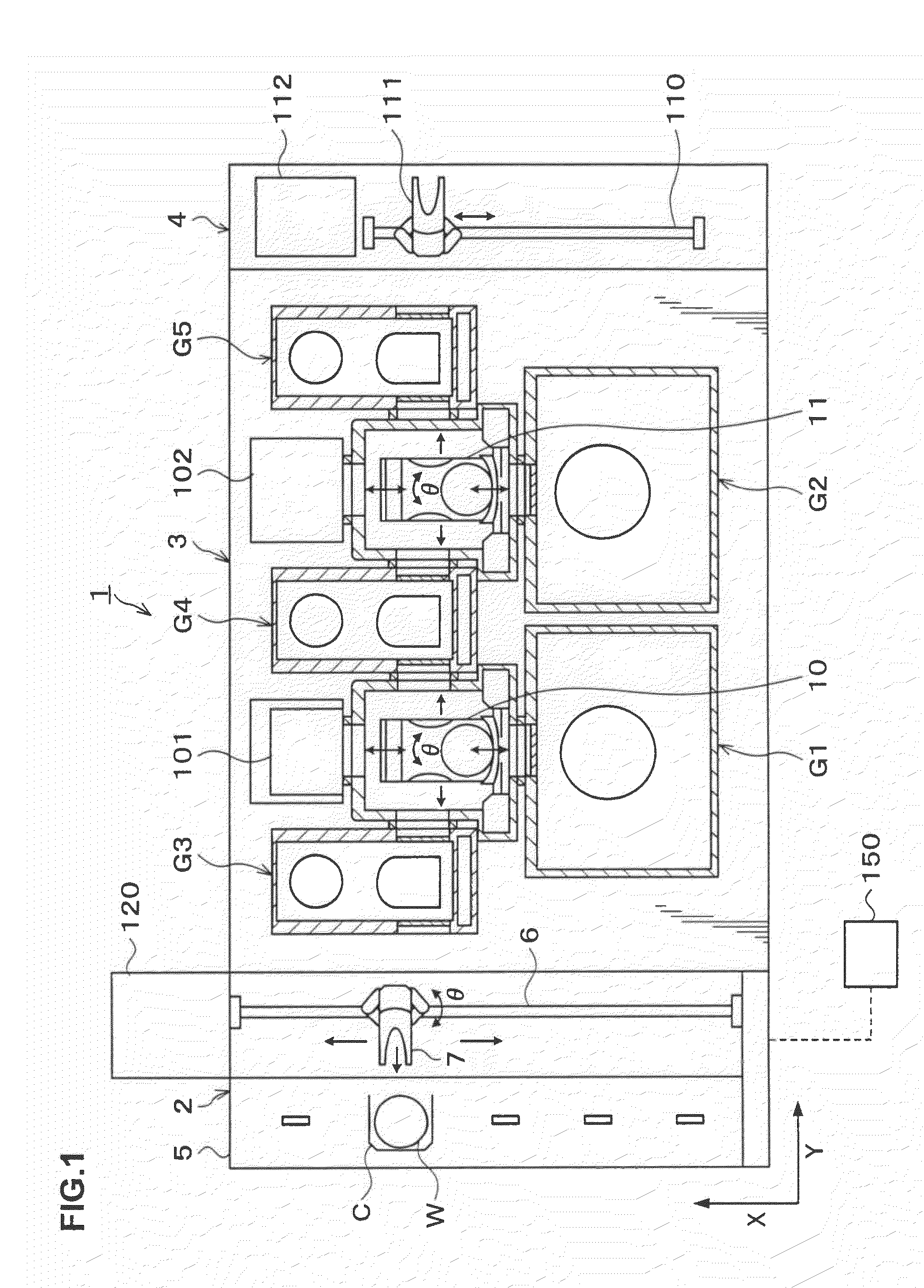
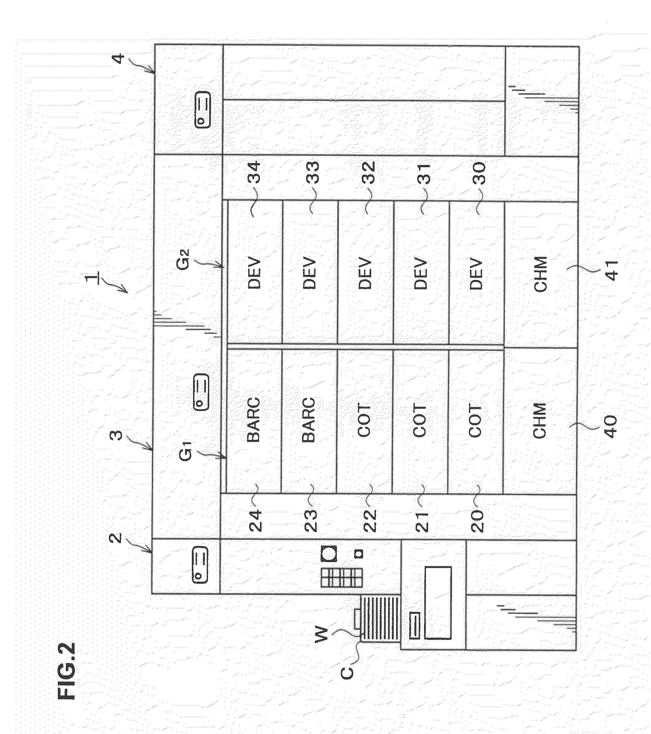
[0040]Hereinafter, a preferred embodiment of the present invention will be described. FIG. 1 is a plan view showing the outline of a configuration of a coating and developing treatment system 1 incorporating a temperature setting apparatus for a thermal processing plate according to the embodiment, FIG. 2 is a front view of the coating and developing treatment system 1, and FIG. 3 is a rear view of the coating and developing treatment system 1.

[0041]The coating and developing treatment system 1 has, as shown in FIG. 1, a configuration in which, for example, a cassette station 2 for transferring, for example, 25 wafers W per cassette as a unit from / to the outside into / from the coating and developing treatment system 1 and transferring the wafers W into / out of a cassette C; a processing station 3 including a plurality of various kinds of processing and treatment units, which are multi-tiered, each for performing predetermined processing or treatment in a manner of single wafer process...


PUM

PropertyMeasurementUnit
temperatureaaaaaaaaaa
in-plane temperatureaaaaaaaaaa

Abstract

In the present invention, a thermal plate of a PEB unit is divided into a plurality of thermal plate regions, and a temperature is settable for each of the thermal plate regions. A temperature correction value for adjusting the temperature within the thermal plate is settable for each of the thermal plate regions of the thermal plate. The line widths within the substrate which has been subjected to the photolithography process are measured, and an improvement in-plane tendency Za improved by change of the temperature settings is subtracted from an in-plane tendency Z of the measured line widths within the substrate to calculate an in-plane tendency Zb of the line widths within the substrate after change of temperature settings. The improvement in-plane tendency Za is calculated using the following expression.Za=−1×α×MT (α: a resist heat sensitivity, M: a calculation model, and T: temperature correction values for thermal plate regions).

Description

BACKGROUND OF THE INVENTION[0001]1. Field of the Invention[0002]The present invention relates to a temperature setting method of a thermal processing plate, a computer-readable recording medium recording a program thereon, and a temperature setting apparatus for a thermal processing plate.[0003]2. Description of the Related Art[0004]In a photolithography process in manufacturing, for example, a semiconductor device, for example, a resist coating treatment of applying a resist solution onto a wafer to form a resist film, exposure processing of exposing the resist film into a predetermined pattern, heating processing of accelerating the chemical reaction in the resist film after exposure (post-exposure baking), and developing treatment of developing the exposed resist film are performed in sequence, so that the series of wafer processing forms a predetermined resist pattern on the wafer.[0005]For example, the heating processing such as the above-described post-exposure baking is usual...

Claims


Application Information

Patent Timeline
Patent Type & Authority Patents(United States)
IPC IPC(8): H05B1/02
CPCG05D23/1932H01L21/67248G03F7/168G03F7/70625H01L21/67098
Inventor JYOUSAKA, MEGUMIKONISHI, YOSHITAKA
Owner TOKYO ELECTRON LTD
Why Eureka
Try Eureka